Page 533 of 1897
BR15B-01
BR-58
- BRAKEPRECHARGE PUMP
1457 Author�: Date�:
2001 AVALON (RM808U)
INSTALLATION
Installation is in the reverse order of removal (See page BR-57).
HINT:
�After installation, fill the brake reservoir with brake fluid, bleed brake system (See page BR-4).
�Check for fluid leaks.
Page 538 of 1897
BR0LF-03
BR-42
- BRAKEREAR BRAKE CALIPER
1441 Author�: Date�:
2001 AVALON (RM808U)
INSTALLATION
Installation is in the reverse order of removal (See page BR-38).
HINT:
�After installation, fill the brake reservoir with brake fluid, bleed brake system (See page BR-4).
�Check for fluid leaks.
Page 540 of 1897

BR0LB-02
F09725
BR-38
- BRAKEREAR BRAKE CALIPER
1437 Author�: Date�:
2001 AVALON (RM808U)
REMOVAL
1. REMOVE REAR WHEEL
Remove the wheel and temporarily fasten the disc with hub
nuts.
Torque: 103 N´m (1,050 kgf´cm, 76 ft´lbf)
2. DISCONNECT FLEXIBLE HOSE
(a) Remove the union bolt and 2 gaskets from the caliper,
then disconnect the flexible hose from the caliper.
Torque: 29 N´m (300 kgf´cm, 22 ft´lbf)
HINT:
At the time of installation, insert the flexible hose lock securely
in the lock hole in the caliper.
(b) Use a container to catch the brake fluid as it drains out.
3. REMOVE CALIPER
(a) Remove the 2 installation bolts.
Torque: 34 N´m (350 kgf´cm, 25 ft´lbf)
NOTICE:
At the time of installation, insert the sliding pin with sliding
bushing into the bottom side.
(b) Remove the caliper from the torque plate.
4. REMOVE 2 BRAKE PADS WITH ANTI- SQUEAL
SHIMS
5. REMOVE 4 PAD SUPPORT PLATES
NOTICE:
There should be no oil or grease adhering to the friction
surfaces of the pads or disc.
Page 542 of 1897

BR0L9-03
F09722
F09723
R10387
- BRAKEREAR BRAKE PAD
BR-35
1434 Author�: Date�:
2001 AVALON (RM808U)
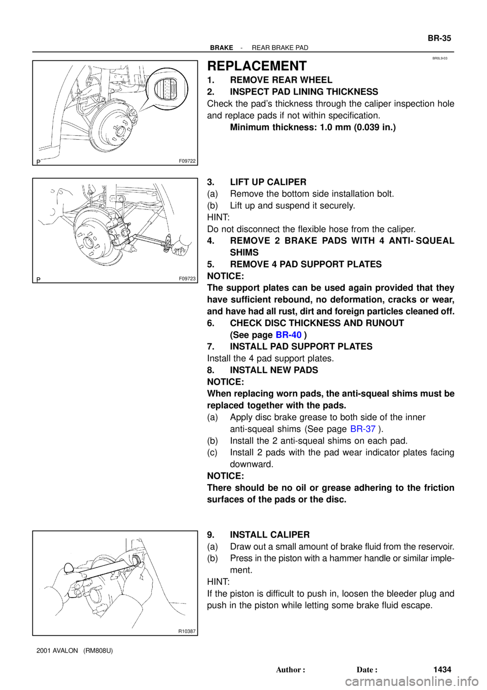
REPLACEMENT
1. REMOVE REAR WHEEL
2. INSPECT PAD LINING THICKNESS
Check the pad's thickness through the caliper inspection hole
and replace pads if not within specification.
Minimum thickness: 1.0 mm (0.039 in.)
3. LIFT UP CALIPER
(a) Remove the bottom side installation bolt.
(b) Lift up and suspend it securely.
HINT:
Do not disconnect the flexible hose from the caliper.
4. REMOVE 2 BRAKE PADS WITH 4 ANTI- SQUEAL
SHIMS
5. REMOVE 4 PAD SUPPORT PLATES
NOTICE:
The support plates can be used again provided that they
have sufficient rebound, no deformation, cracks or wear,
and have had all rust, dirt and foreign particles cleaned off.
6. CHECK DISC THICKNESS AND RUNOUT
(See page BR-40)
7. INSTALL PAD SUPPORT PLATES
Install the 4 pad support plates.
8. INSTALL NEW PADS
NOTICE:
When replacing worn pads, the anti-squeal shims must be
replaced together with the pads.
(a) Apply disc brake grease to both side of the inner
anti-squeal shims (See page BR-37).
(b) Install the 2 anti-squeal shims on each pad.
(c) Install 2 pads with the pad wear indicator plates facing
downward.
NOTICE:
There should be no oil or grease adhering to the friction
surfaces of the pads or the disc.
9. INSTALL CALIPER
(a) Draw out a small amount of brake fluid from the reservoir.
(b) Press in the piston with a hammer handle or similar imple-
ment.
HINT:
If the piston is difficult to push in, loosen the bleeder plug and
push in the piston while letting some brake fluid escape.
Page 543 of 1897
F09723
BR-36
- BRAKEREAR BRAKE PAD
1435 Author�: Date�:
2001 AVALON (RM808U)
(c) Install the caliper.
(d) Install the installation bolt.
Torque: 34 N´m (350 kgf´cm, 25 ft´lbf)
10. INSTALL REAR WHEEL
Torque: 103 N´m (1,050 kgf´cm, 76 ft´lbf)
11. DEPRESS BRAKE PEDAL SEVERAL TIMES
12. CHECK THAT FLUID LEVEL IS AT MAX LINE
Page 547 of 1897

BR0KG-05
BR-2
- BRAKETROUBLESHOOTING
1401 Author�: Date�:
2001 AVALON (RM808U)
TROUBLESHOOTING
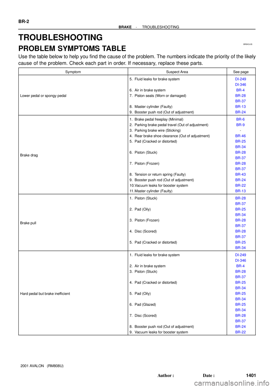
PROBLEM SYMPTOMS TABLE
Use the table below to help you find the cause of the problem. The numbers indicate the priority of the likely
cause of the problem. Check each part in order. If necessary, replace these parts.
SymptomSuspect AreaSee page
Lower pedal or spongy pedal
5. Fluid leaks for brake system
6. Air in brake system
7. Piston seals (Worn or damaged)
8. Master cylinder (Faulty)
9. Booster push rod (Out of adjustment)DI-249
DI-346
BR-4
BR-28
BR-37
BR-13
BR-24
Brake drag
1. Brake pedal freeplay (Minimal)
2. Parking brake pedal travel (Out of adjustment)
3. Parking brake wire (Sticking)
4. Rear brake shoe clearance (Out of adjustment)
5. Pad (Cracked or distorted)
6. Piston (Stuck)
7. Piston (Frozen)
8. Tension or return spring (Faulty)
9. Booster push rod (Out of adjustment)
10.Vacuum leaks for booster system
11. Master cylinder (Faulty)BR-6
BR-9
-
BR-46
BR-25
BR-34
BR-28
BR-37
BR-28
BR-37
BR-43
BR-24
BR-22
BR-13
Brake pull
1. Piston (Stuck)
2. Pad (Oily)
3. Piston (Frozen)
4. Disc (Scored)
5. Pad (Cracked or distorted)BR-28
BR-37
BR-25
BR-34
BR-28
BR-37
BR-28
BR-37
BR-25
BR-34
Hard pedal but brake inefficient
1. Fluid leaks for brake system
2. Air in brake system
3. Piston (Stuck)
4. Pad (Cracked or distorted)
5. Pad (Oily)
6. Pad (Glazed)
7. Disc (Scored)
8. Booster push rod (Out of adjustment)
9. Vacuum leaks for booster systemDI-249
DI-346
BR-4
BR-28
BR-37
BR-25
BR-34
BR-25
BR-34
BR-25
BR-34
BR-28
BR-37
BR-24
BR-22
Page 568 of 1897
CO02K-03
- COOLINGCOOLANT
CO-1
1194 Author�: Date�:
2001 AVALON (RM808U)
COOLANT
INSPECTION
1. CHECK ENGINE COOLANT LEVEL AT RADIATOR RESERVOIR
The engine coolant level should be between the ºLOWº and ºFULLº lines, when the engine is cold.
If low, check for leaks and add ''Toyota Long Life Coolantº or Equivalent up to the ºFULLº line.
2. CHECK ENGINE COOLANT QUALITY
(a) Remove the radiator cap from the water outlet.
CAUTION:
To avoid the danger of being burned, do not remove the radiator cap while the engine and radiator
are still hot, as fluid and steam can be blown out under pressure.
(b) There should not be any excessive deposits of rust or scale around the radiator cap or water outlet
filler hole, and the coolant should be free from oil.
If excessively dirty, clean the coolant passages and replace the coolant.
(c) Reinstall the radiator cap.
Page 569 of 1897

CO02L-03
B09030Drain PlugDrain Plug
CO-2
- COOLINGCOOLANT
1195 Author�: Date�:
2001 AVALON (RM808U)
REPLACEMENT
1. DRAIN ENGINE COOLANT
(a) Remove the radiator cap from the water outlet.
CAUTION:
To avoid the danger of being burned, do not remove the ra-
diator cap while the engine and radiator are still hot, as fluid
and steam can be blown out under pressure.
(b) Loosen the radiator drain plug and engine drain plugs,
and drain the coolant.
(c) Close the drain plugs.
Torque:
RH engine drain plug on cylinder block side cover:
7 N´m (70 kgf´cm, 61 in.´lbf)
LH engine drain plug on union:
13 N´m (130 kgf´cm, 9 ft´lbf)
2. FILL ENGINE COOLANT
(a) Slowly fill the system with coolant.
�Use of improper coolants may damage engine cool-
ing system.
�Use ºToyota Long life Coolantº or equivalent and
mix it with plan water according to the manufactur-
er's directions.
�Using of coolant which includes more than 50 %
(freezing protection down to -35°C (-31°F) or 60 %
(freezing protection down to -50°C (-58°F)) of eth-
ylene-glycol is recommended but not more than 70
%.
NOTICE:
�Do not use an alcohol type coolant or plain water
alone.
�The coolant should be mixed with plain water (prefer-
ably demineralized water or distilled water).
Capacity: 9.0 liters (9.5 US qts, 7.9 lmp. qts)
(b) Install the radiator cap.
(c) Start the engine, and bleed the cooling system.
(d) If necessary, refill coolant into the reservoir up to the
ºFULLº line.
3. CHECK ENGINE COOLANT FOR LEAKS
4. CHECK ENGINE COOLANT SPECIFIC GRAVITY COR-
RECTLY