Page 583 of 1897

ON-VEHICLE INSPECTION
1. REMOVE RADIATOR C")
CO09I-02
Z00570
Radiator Cap Tester
30° or More
Radiator Cap
P13014
Radiator Cap
Tester CO-14
- COOLINGRADIATOR
1207 Author�: Date�:
2001 AVALON (RM808U)
ON-VEHICLE INSPECTION
1. REMOVE RADIATOR CAP
CAUTION:
To avoid the danger of being burned, do not remove the ra-
diator cap while the engine and radiator are still hot, as fluid
and steam can be blow out under pressure.
2. INSPECT RADIATOR CAP
NOTICE:
�If the radiator cap has contaminations, always rinse
it with water.
�When performing steps (a) and (b) below, keep the ra-
diator cap tester at an angle of over 30° above the hor-
izontal.
�Before using a radiator cap tester, wet the relief valve
and pressure valve with engine coolant or water.
(a) Using a radiator cap tester, slowly pump the tester and
check that air is coming from the vacuum valve.
Pump speed: 1 push/(3 seconds or more)
NOTICE:
Push the pump at a constant speed.
If air is not coming from the vacuum valve, replace the radiator
cap.
(b) Pump the tester and measure the relief valve opening
pressure.
Pump speed: 1 push within 1 second
NOTICE:
This pump speed is for the first pump only (in order to close
the vacuum valve). After this, the pump speed can be re-
duced.
Standard opening pressure:
83 - 113 kPa (0.85 - 1.15 kgf/cm
2, 12.1 - 16.4 psi)
Minimum opening pressure:
69 kPa (0.7 kgf/cm
2, 10.0 psi)
HINT:
Use the tester's maximum reading as the opening pressure.
If the opening pressure is less than minimum, replace the radia-
tor cap.
3. INSPECT COOLING SYSTEM FOR LEAKS
(a) Fill the radiator with coolant, and attach a radiator cap tes-
ter.
(b) Warm up the engine.
(c) Pump it to 127 kPa (1.3 kgf/cm
2, 18.5 psi), and check that
the pressure does not drop.
If the pressure drops, check the hoses, radiator or water pump
for leaks. If no external leaks are found, check the heater core,
cylinder block and cylinder head.
4. REINSTALL RADIATOR CAP
Page 587 of 1897

REMOVAL
HINT:
At the time of installation, please refer to the following items.
�Start the engine, and check for coo")
CO0WT-01
B09040
- COOLINGRADIATOR
CO-17
1210 Author�: Date�:
2001 AVALON (RM808U)
REMOVAL
HINT:
At the time of installation, please refer to the following items.
�Start the engine, and check for coolant and A/T fluid
leaks.
�Check the A/T fluid level (See page DI-160).
1. REMOVE BATTERY AND BATTERY TRAY
2. REMOVE ENGINE UNDER COVER
3. DRAIN ENGINE COOLANT
4. DISCONNECT NO.3 ENGINE ROOM RELAY BLOCK
FROM RADIATOR
5. DISCONNECT NO.1 COOLING FAN CONNECTOR
6. DISCONNECT WIRE CLAMPS FROM NO.1 FAN
SHROUD
7. DISCONNECT NO.2 COOLING FAN CONNECTOR
8. DISCONNECT NO.1 ECT SWITCH WIRE CONNECTOR
9. DISCONNECT WIRE CLAMPS FROM NO.2 FAN
SHROUD
10. DISCONNECT UPPER RADIATOR HOSE FROM RA-
DIATOR
11. DISCONNECT LOWER RADIATOR HOSE FROM RA-
DIATOR
12. DISCONNECT A/T OIL COOLER HOSES FROM RA-
DIATOR
13. REMOVE RADIATOR AND COOLING FANS AS-
SEMBLY
(a) Remove the 2 bolts and 2 upper supports.
Torque: 12.8 N´m (130 kgf´cm, 9 ft´lbf)
(b) Lift out the radiator, and remove the radiator and cooling
fans assembly.
(c) Remove the 2 lower supports.
14. REMOVE NO.1 ECT SWITCH
15. REMOVE NO.1 COOLING FAN FROM RADIATOR
Remove the 2 bolts and cooling fan.
Torque: 5.0 N´m (50 kgf´cm, 44 in.´lbf)
16. REMOVE NO.2 COOLING FAN FROM RADIATOR
Remove the 2 bolts and cooling fan.
Torque: 5.0 N´m (50 kgf´cm, 44 in.´lbf)
Page 602 of 1897
F09801
ABS Actuator
and ECU
A713
Battery J/B No. 3A21
Active Light Relay
Multi DisplayY-B
BRAKEPKB
PKB
Ignition Switch
IF1 A721
EBDW IE15
Y-B
6 5
8 3 Y-G
3B14
3A
6 3B
5
Y-G
B4
15R-W
IE116
R-Y
Y-G
1
P3
Parking
Brake
Switch W-BBody ECU
J1
J/CDriver Side J/B
B1
Bake Fluid
Level Warning
Switch
J/B No. 3
R-W3H
153B
15
15
3A
12
1I8
1H
R-W
1
2
B B
Engine Room J/BDriver Side J/BGAUGE No. 1 IG1 Relay
4
2D4
2F
W-B
ED
R-WR-WIC17
M63
M64R-B
J/B No. 4
13
4F4
4D
R-B
10
1D 1
2
3 44
1C 3
1B1
1G W
IGW-BEngine Room J/BEngine Room R/B No. 57
BAM1
B-L
FL Block
ALT5 512 1
2H 1
2G
1
F8
F10F61
BFL MAIN W-B
142
W-R
W-L
W-L R-Y DI-240
- DIAGNOSTICSANTI-LOCK BRAKE SYSTEM WITH ELECTRONIC
BRAKE FORCE DISTRIBUTION (EBD)
396 Author�: Date�:
2001 AVALON (RM808U)
BRAKE Warning Light Circuit
CIRCUIT DESCRIPTION
The BRAKE warning light lights up when the brake fluid is insufficient, parking brake is applied or the EBD
is defective.
WIRING DIAGRAM
DI6NL-02
Page 603 of 1897
- DIAGNOSTICSANTI-LOCK BRAKE SYSTEM WITH ELECTRONIC
BRAKE FORCE DISTRIBUTION (EBD)DI-241
397 Author�: Date�:
2001 AVALON (RM808U)
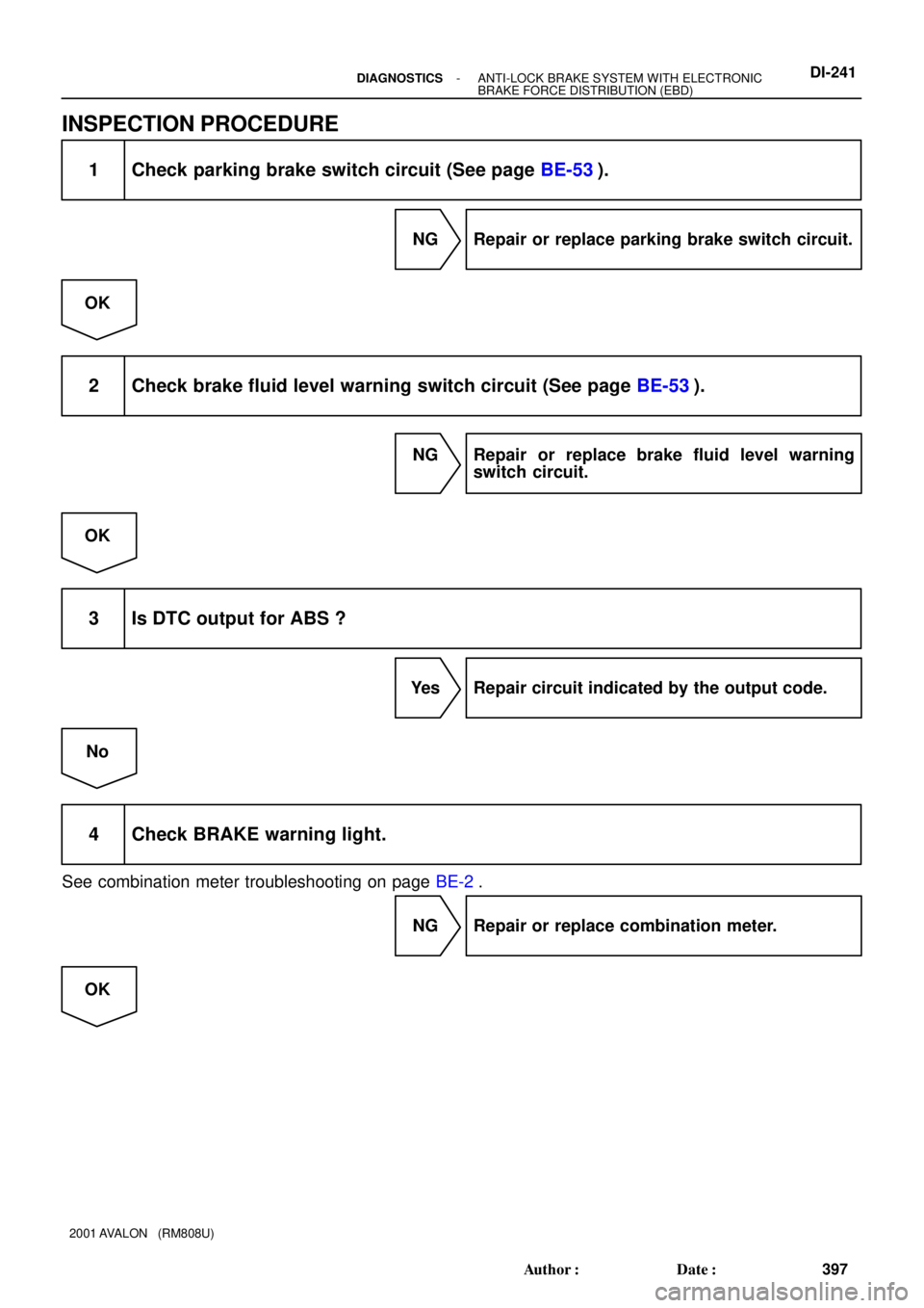
INSPECTION PROCEDURE
1 Check parking brake switch circuit (See page BE-53).
NG Repair or replace parking brake switch circuit.
OK
2 Check brake fluid level warning switch circuit (See page BE-53).
NG Repair or replace brake fluid level warning
switch circuit.
OK
3 Is DTC output for ABS ?
Yes Repair circuit indicated by the output code.
No
4 Check BRAKE warning light.
See combination meter troubleshooting on page BE-2.
NG Repair or replace combination meter.
OK
Page 605 of 1897
F07888
- DIAGNOSTICSANTI-LOCK BRAKE SYSTEM WITH ELECTRONIC
BRAKE FORCE DISTRIBUTION (EBD)DI-249
405 Author�: Date�:
2001 AVALON (RM808U)
Check for Fluid Leakage
Check for fluid leakage from actuator or hydraulic lines.
DI6NP-01
Page 631 of 1897

P. DI-212Items inside
are titles of pages in this manual,
with the page number in the bottom")
DI6N5-01
Vehicle Brought to Workshop
Customer Problem Analysis
P. DI-21 1
Check and Clear DTC (Precheck)
P. DI-212Items inside
are titles of pages in this manual,
with the page number in the bottom portion. See
the pages for detailed explanations.
Problem Symptom ConfirmationSymptom Simulation
P. IN-20
Symptom
does not occur
Symptom
occurs
DTC Check
Sensor CheckCircuit Inspection
P. DI-219 - DI-247
DTC Chart
P. DI-215 Malfunction codeProblem Symptoms Table
P. DI-218
Check for Fluid Leakage
P. DI-249
Identification of Problem
Normal code
Repair
Confirmation Test
End
1
2
3
4
5
67
89
10
11
P. DI-212
Fail safe function:
When a failure occurs in the ABS system, the ABS warning light is lit and the ABS operation is prohibited. In addition
to this, when the failure which disables the EBD operation occurs, the brake warning light is lit as well and EBD
operation is prohibited. DI-210
- DIAGNOSTICSANTI-LOCK BRAKE SYSTEM WITH ELECTRONIC
BRAKE FORCE DISTRIBUTION (EBD)
366 Author�: Date�:
2001 AVALON (RM808U)
ANTI-LOCK BRAKE SYSTEM WITH ELECTRONIC BRAKE
FORCE DISTRIBUTION (EBD)
HOW TO PROCEED WITH TROUBLESHOOTING
Troubleshoot in accordance with the procedure on the following pages.
Page 633 of 1897

DI6N7-01
F07879
F02201
E1Tc
DLC1
F00103
Normal Code
0.25 sec.
0.25 sec. 0.5 sec.
ON
OFF
ON
OFF0.5 sec. 0.5 sec.
Code 11 and 21
4 sec.1.5 sec.
2.5 sec.
Code 11 Code 21
DI-212- DIAGNOSTICSANTI-LOCK BRAKE SYSTEM WITH ELECTRONIC
BRAKE FORCE DISTRIBUTION (EBD)
368 Author�: Date�:
2001 AVALON (RM808U)
PRE-CHECK
1. DIAGNOSIS SYSTEM
(a) Release the parking brake pedal.
(b) Check the indicator.
When the ignition switch is turned ON, check that the ABS
warning light and BRAKE warning light goes on for
approx. 3 seconds.
HINT:
�When the parking brake is applied or the level of the brake
fluid is low, the BRAKE warning light is lit.
�If the indicator check result is not normal, proceed to trou-
bleshooting for the ABS warning light circuit or BRAKE
warning light circuit (See page DI-243, DI-240).
(c) Check the DTC.
(1) Using SST, connect terminals Tc and E
1 of DLC1.
SST 09843-18020
(2) Turn the ignition switch ON and read the DTC from
the ABS warning light on the combination meter.
HINT:
�If no codes appears, inspect the diagnostic circuit or ABS
warning light circuit (See page DI-245 or DI-243).
�As an example, the blinking patterns for normal code and
codes 11 and 21 are shown on the left.
(3) Codes are explained in the code table on page
DI-215.
(4) After completing the check, disconnect terminals Tc
and E
1, and turn off the display.
If 2 or more malfunction codes are identified at the
same time, the lowest numbered DTC will be dis-
played 1st.
Page 646 of 1897

F09824
Battery
FL MAIN F10 F8
F611 1
ALT
BFL BlockB-L 2G 2H1 1 Engine Room J/B B5512 AM1 Engine Room R/B No. 5 W-LIF17
W-L
2
IG1 AM1 4Ignition Switch W-R W
1C 1G
1B 1D
4
4 3 1
1
2
3 10 GAUGE No. 1 Driver Side J/B
IG1 Relay
W-B
IG
ED CUP
BRAKE
Multi DisplayM6 M3M6R-B
3 4
74D 4F13
4 J/B No. 4
R-B
L-O L-O6
IL1
R-WR-W
R-W
R-W
7
IC13A21
Active
Light
RelayR-Y 8A20
6040 74 68
32 ABS & BA &
TRAC & VSC ECU
FSS LBL PKB EBDW SP1
T5
T5
T5
T5 T5
Y-G
L-B
BR (Shielded)15
25 16
2
11
LBL LVL2PKB2BRL
PKB
Y-G Y-G
R-W
R-WJ/B No. 3
3B 3A
3A 3B 5
15
15 14
1Driver Side J/B
B1
Brake Fluid Level
Warning Switch Translate ECU
1H
1I 12
8
R-W
1 2
W-B J1 J/C
B B
W-BEngine Room J/B
44
2D2FW-B P3
Parking
Brake
SwitchA20
A20
A20
A20 DI-330
- DIAGNOSTICSABS WITH EBD & BA & TRAC & VSC SYSTEM
486 Author�: Date�:
2001 AVALON (RM808U)
BRAKE Warning Light Circuit
CIRCUIT DESCRIPTION
�The BRAKE warning light lights up when the brake fluid is insufficient, when the parking brake is ap-
plied or when the EBD is defective.
�If the translate ECU detects trouble, it makes VSC warning light lights up while prohibiting VSC & TRAC
control. At this time, the ECU records a DTC in memory. Connect terminals Tc and E
1 of the DLC1 or
DLC2 to make BRAKE warning light blink and output the DTC.
WIRING DIAGRAM
DI6OK-02