Page 100 of 1897
Q06530
Q10038
D07216
Q10037
- AUTOMATIC TRANSAXLEAUTOMATIC TRANSAXLE UNIT
AX-37
1327 Author�: Date�:
2001 AVALON (RM808U)
16. REMOVE EXHAUST MANIFOLD BRACKET MOUNT-
ING BOLT
Torque: 34 N´m (350 kgf´cm, 25 ft´lbf)
17. REMOVE 5 TRANSAXLE-TO-ENGINE BOLTS AND
DISCONNECT GROUND TERMINAL
Torque: 66 N´m (670 kgf´cm, 48 ft´lbf)
18. RAISE AND SUPPORT VEHICLE SECURELY
19. REMOVE LH AND RH FRONT WHEELS
Torque: 103 N´m (1,050 kgf´cm, 76 ft´lbf)
20. REMOVE DIFFERENTIAL FLUID DRAIN PLUG AND
GASKET
Torque: 49 N´m (500 kgf´cm, 36 ft´lbf)
HINT:
At the time of installation, please refer to the following item.
Replace the used gasket with a new gasket.
21. DRAIN DIFFERENTIAL FLUID
22. REMOVE LH AND RH FRONT DRIVE SHAFTS (See
page SA-16)
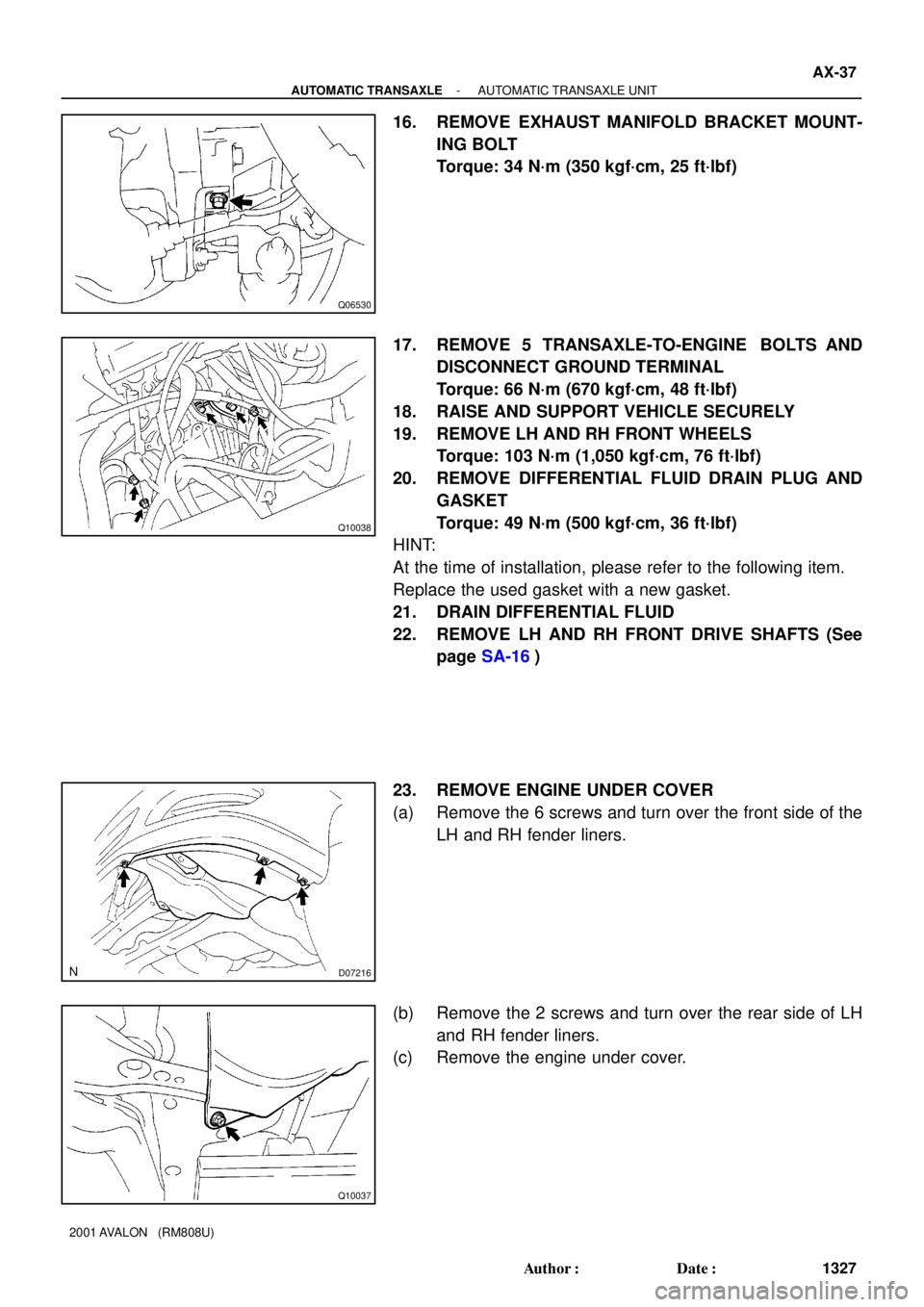
23. REMOVE ENGINE UNDER COVER
(a) Remove the 6 screws and turn over the front side of the
LH and RH fender liners.
(b) Remove the 2 screws and turn over the rear side of LH
and RH fender liners.
(c) Remove the engine under cover.
Page 144 of 1897

VALVE BODY ASSEMBLY
ON-VEHICLE REPAIR
1. CLEAN TRANSAXLE EXTER")
AX05D-03
AT3785
AT0103
D01019
Q05728
Connector AX-6
- AUTOMATIC TRANSAXLEVALVE BODY ASSEMBLY
1296 Author�: Date�:
2001 AVALON (RM808U)
VALVE BODY ASSEMBLY
ON-VEHICLE REPAIR
1. CLEAN TRANSAXLE EXTERIOR
To help prevent contamination, clean the exterior of the trans-
axle.
2. DRAIN ATF
Using a hexagon wrench, remove the drain plug and drain the
fluid into the suitable container.
3. REMOVE OIL PAN AND GASKET
NOTICE:
Some fluid will remain in the oil pan.
Remove oil pan bolts, and carefully remove the pan assembly.
Discard the gasket.
4. EXAMINE PARTICLES IN PAN
Remove the magnets and use them to collect any steel chips.
Look at the chips and particles in the pan and magnet carefully
to anticipate what type of wear you will find in the transaxle.
�Steel (magnetic): bearing, gear and plate wear
�Brass (non-magnetic): bushing wear
5. REMOVE OIL STRAINER AND APPLY PIPE BRACKET
(a) Remove the 3 bolts and oil strainer.
NOTICE:
Be careful as oil will come out of the strainer when it is re-
moved.
(b) Remove the 3 bolts and apply pipe bracket.
6. REMOVE OIL PIPE
Pry up both pipe ends with a large screwdriver and remove the
5 pipes.
7. DISCONNECT 3 SOLENOID CONNECTORS
Page 149 of 1897
Z19256
BA
B A
AT3741
AT3785
- AUTOMATIC TRANSAXLEVALVE BODY ASSEMBLY
AX-1 1
1301 Author�: Date�:
2001 AVALON (RM808U)
24. INSTALL OIL STRAINER AND APPLY PIPE BRACKET
Install the oil strainer and apply pipe bracket with the 6 bolts.
Torque:
Bolt A: 10 N´m (100 kgf´cm, 7 ft´lbf)
Bolt B: 11 N´m (110 kgf´cm, 8 ft´lbf)
Bolt length:
Bolt A: 22 mm (0.866 in.)
Bolt B: 53 mm (2.087 in.)
25. INSTALL MAGNET IN PLACE
Install the 3 magnets in the indentations of the oil pan, as shown
in the illustration.
NOTICE:
Make sure that the magnet does not interfere with the oil
pipes.
26. INSTALL OIL PAN AND GASKET
(a) Install the oil pan and a new gasket.
(b) Install the 17 bolts.
Torque: 7.8 N´m (80 kgf´cm, 69 in.´lbf)
27. INSTALL DRAIN PLUG
Install a new gasket and drain plug.
Torque: 49 N´m (500 kgf´cm, 36 ft´lbf)
28. FILL ATF AND CHECK FLUID LEVEL
(See page DI-160)
Page 473 of 1897
H12169
BO-80
- BODYSLIDING ROOF
1865 Author�: Date�:
2001 AVALON (RM808U)
5. REMOVE SLIDING ROOF HOUSING
(a) Disconnect the 4 drain hoses from the housing.
(b) Remove the 8 bolts and 4 brackets.
Torque: 5.4 (55 kgf´cm, 48 in.´lbf)
(c) Remove the 6 nuts, then remove the sliding roof housing.
Torque: 5.4 (55 kgf´cm, 48 in.´lbf)
Page 517 of 1897
BR0L3-04
R02840
- BRAKEFRONT BRAKE CALIPER
BR-29
1428 Author�: Date�:
2001 AVALON (RM808U)
REMOVAL
1. REMOVE FRONT WHEEL
Remove the wheel and temporarily fasten the disc with hub
nuts.
Torque: 103 N´m (1,050 kgf´cm, 76 ft´lbf)
2. DISCONNECT FLEXIBLE HOSE
(a) Remove the union bolt and 2 gaskets from the caliper,
then disconnect the flexible hose from the caliper.
Torque: 29 N´m (300 kgf´cm, 22 ft´lbf)
HINT:
At the time of installation, install the flexible hose lock securely
in the lock hole in the caliper.
(b) Use a container to catch the brake fluid as it drains out.
3. REMOVE CALIPER
(a) Remove the 2 installation bolts.
Torque: 34 N´m (350 kgf´cm, 25 ft´lbf)
(b) Remove the caliper from the torque plate.
4. REMOVE 2 BRAKE PADS WITH ANTI- SQUEAL
SHIMS
5. REMOVE 2 PAD SUPPORT PLATES
Page 540 of 1897

REMOVAL
1. REMOVE REAR WHEEL
Remove the wheel and temporarily fasten the disc with hub
nuts.
Torque: 103 N´")
BR0LB-02
F09725
BR-38
- BRAKEREAR BRAKE CALIPER
1437 Author�: Date�:
2001 AVALON (RM808U)
REMOVAL
1. REMOVE REAR WHEEL
Remove the wheel and temporarily fasten the disc with hub
nuts.
Torque: 103 N´m (1,050 kgf´cm, 76 ft´lbf)
2. DISCONNECT FLEXIBLE HOSE
(a) Remove the union bolt and 2 gaskets from the caliper,
then disconnect the flexible hose from the caliper.
Torque: 29 N´m (300 kgf´cm, 22 ft´lbf)
HINT:
At the time of installation, insert the flexible hose lock securely
in the lock hole in the caliper.
(b) Use a container to catch the brake fluid as it drains out.
3. REMOVE CALIPER
(a) Remove the 2 installation bolts.
Torque: 34 N´m (350 kgf´cm, 25 ft´lbf)
NOTICE:
At the time of installation, insert the sliding pin with sliding
bushing into the bottom side.
(b) Remove the caliper from the torque plate.
4. REMOVE 2 BRAKE PADS WITH ANTI- SQUEAL
SHIMS
5. REMOVE 4 PAD SUPPORT PLATES
NOTICE:
There should be no oil or grease adhering to the friction
surfaces of the pads or disc.
Page 575 of 1897
CO09O-02
B09051
No.1
B09052
No.2
- COOLINGELECTRIC COOLING FAN
CO-27
1220 Author�: Date�:
2001 AVALON (RM808U)
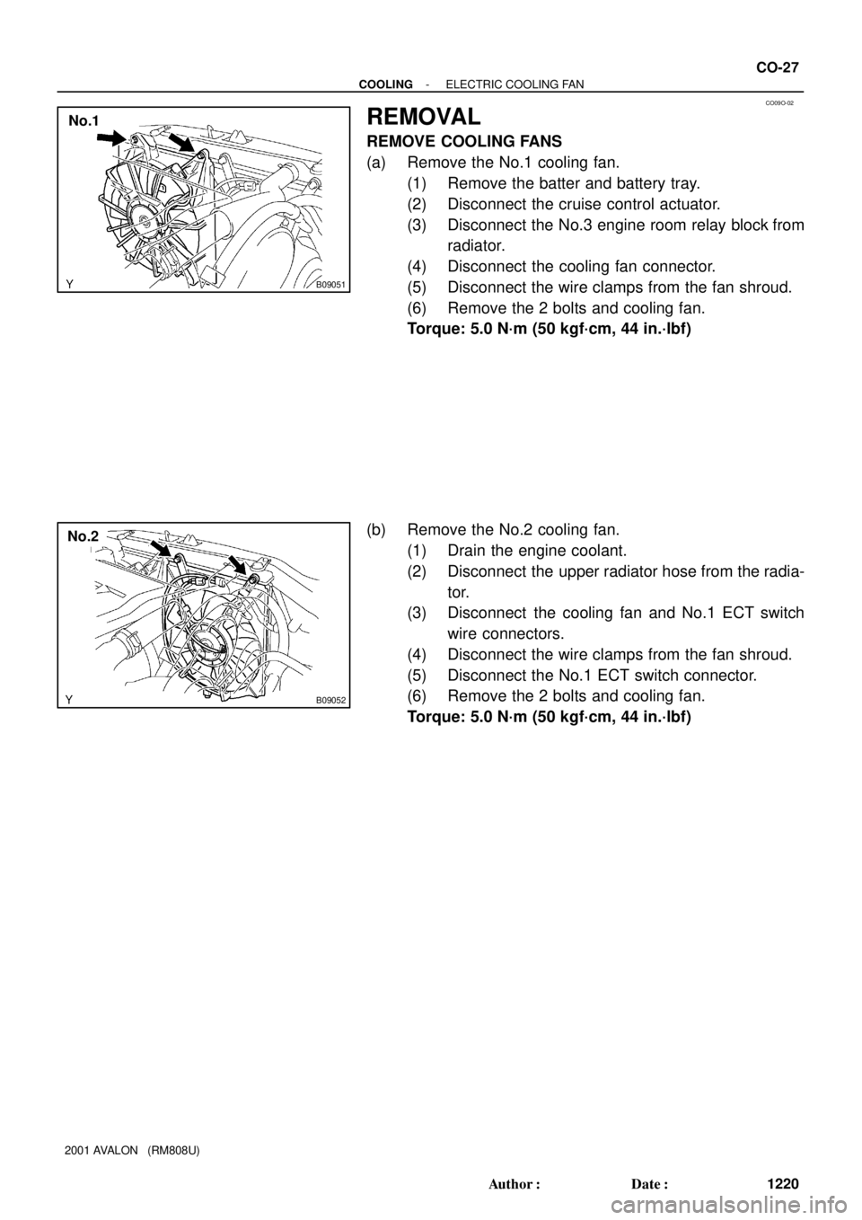
REMOVAL
REMOVE COOLING FANS
(a) Remove the No.1 cooling fan.
(1) Remove the batter and battery tray.
(2) Disconnect the cruise control actuator.
(3) Disconnect the No.3 engine room relay block from
radiator.
(4) Disconnect the cooling fan connector.
(5) Disconnect the wire clamps from the fan shroud.
(6) Remove the 2 bolts and cooling fan.
Torque: 5.0 N´m (50 kgf´cm, 44 in.´lbf)
(b) Remove the No.2 cooling fan.
(1) Drain the engine coolant.
(2) Disconnect the upper radiator hose from the radia-
tor.
(3) Disconnect the cooling fan and No.1 ECT switch
wire connectors.
(4) Disconnect the wire clamps from the fan shroud.
(5) Disconnect the No.1 ECT switch connector.
(6) Remove the 2 bolts and cooling fan.
Torque: 5.0 N´m (50 kgf´cm, 44 in.´lbf)
Page 587 of 1897

REMOVAL
HINT:
At the time of installation, please refer to the following items.
�Start the engine, and check for coo")
CO0WT-01
B09040
- COOLINGRADIATOR
CO-17
1210 Author�: Date�:
2001 AVALON (RM808U)
REMOVAL
HINT:
At the time of installation, please refer to the following items.
�Start the engine, and check for coolant and A/T fluid
leaks.
�Check the A/T fluid level (See page DI-160).
1. REMOVE BATTERY AND BATTERY TRAY
2. REMOVE ENGINE UNDER COVER
3. DRAIN ENGINE COOLANT
4. DISCONNECT NO.3 ENGINE ROOM RELAY BLOCK
FROM RADIATOR
5. DISCONNECT NO.1 COOLING FAN CONNECTOR
6. DISCONNECT WIRE CLAMPS FROM NO.1 FAN
SHROUD
7. DISCONNECT NO.2 COOLING FAN CONNECTOR
8. DISCONNECT NO.1 ECT SWITCH WIRE CONNECTOR
9. DISCONNECT WIRE CLAMPS FROM NO.2 FAN
SHROUD
10. DISCONNECT UPPER RADIATOR HOSE FROM RA-
DIATOR
11. DISCONNECT LOWER RADIATOR HOSE FROM RA-
DIATOR
12. DISCONNECT A/T OIL COOLER HOSES FROM RA-
DIATOR
13. REMOVE RADIATOR AND COOLING FANS AS-
SEMBLY
(a) Remove the 2 bolts and 2 upper supports.
Torque: 12.8 N´m (130 kgf´cm, 9 ft´lbf)
(b) Lift out the radiator, and remove the radiator and cooling
fans assembly.
(c) Remove the 2 lower supports.
14. REMOVE NO.1 ECT SWITCH
15. REMOVE NO.1 COOLING FAN FROM RADIATOR
Remove the 2 bolts and cooling fan.
Torque: 5.0 N´m (50 kgf´cm, 44 in.´lbf)
16. REMOVE NO.2 COOLING FAN FROM RADIATOR
Remove the 2 bolts and cooling fan.
Torque: 5.0 N´m (50 kgf´cm, 44 in.´lbf)