Page 591 of 1897

REMOVAL
HINT:
Removal of the thermostat would have an adverse effect, cau")
CO0SW-02
A10518
5 mm
Hexagon
Wrench
B08906
B06725
B04150
CO-10
- COOLINGTHERMOSTAT
1203 Author�: Date�:
2001 AVALON (RM808U)
REMOVAL
HINT:
Removal of the thermostat would have an adverse effect, caus-
ing a lowering of cooling efficiency. Do not remove the thermo-
stat, even if the engine tends to overheat.
1. DRAIN ENGINE COOLANT
2. REMOVE V-BANK COVER
(a) Using a 5 mm hexagon wrench, remove the 3 cap nuts.
(b) Loosen the V-bank cover fastener counterclockwise.
(c) Remove the V-bank cover.
3. WARM UP ENGINE
Allow the engine to warm up to normal operating temperature.
4. REMOVE AIR CLEANER HOSE WITH RESONATOR
5. DISCONNECT HEATER HOSES
6. DISCONNECT NO.2 ECT SWITCH CONNECTOR
7. DISCONNECT ENGINE WIRE PROTECTOR FROM
WATER INLET AND RH CYLINDER HEAD
Remove the nut and disconnect the clamp, and disconnect the
engine wire protector from the water inlet and cylinder head.
8. DISCONNECT WATER INLET PIPE FROM WATER IN-
LET AND LH CYLINDER HEAD
(a) Remove the bolt, and disconnect the inlet pipe from the
water inlet.
(b) Remove the O-ring from the inlet pipe.
9. REMOVE WATER INLET AND THERMOSTAT
(a) Remove the 3 nuts, water inlet and thermostat.
(b) Remove the gasket from the thermostat.
Page 597 of 1897
CO0WS-01
P12942
CO-6
- COOLINGWATER PUMP
1199 Author�: Date�:
2001 AVALON (RM808U)
REMOVAL
1. DRAIN ENGINE COOLANT
2. REMOVE TIMING BELT (See page EM-15)
3. REMOVE CAMSHAFT TIMING PULLEYS
(See page EM-15)
4. REMOVE NO.2 IDLER PULLEY (See page EM-31)
5. REMOVE NO.3 TIMING BELT COVER
(See page EM-15)
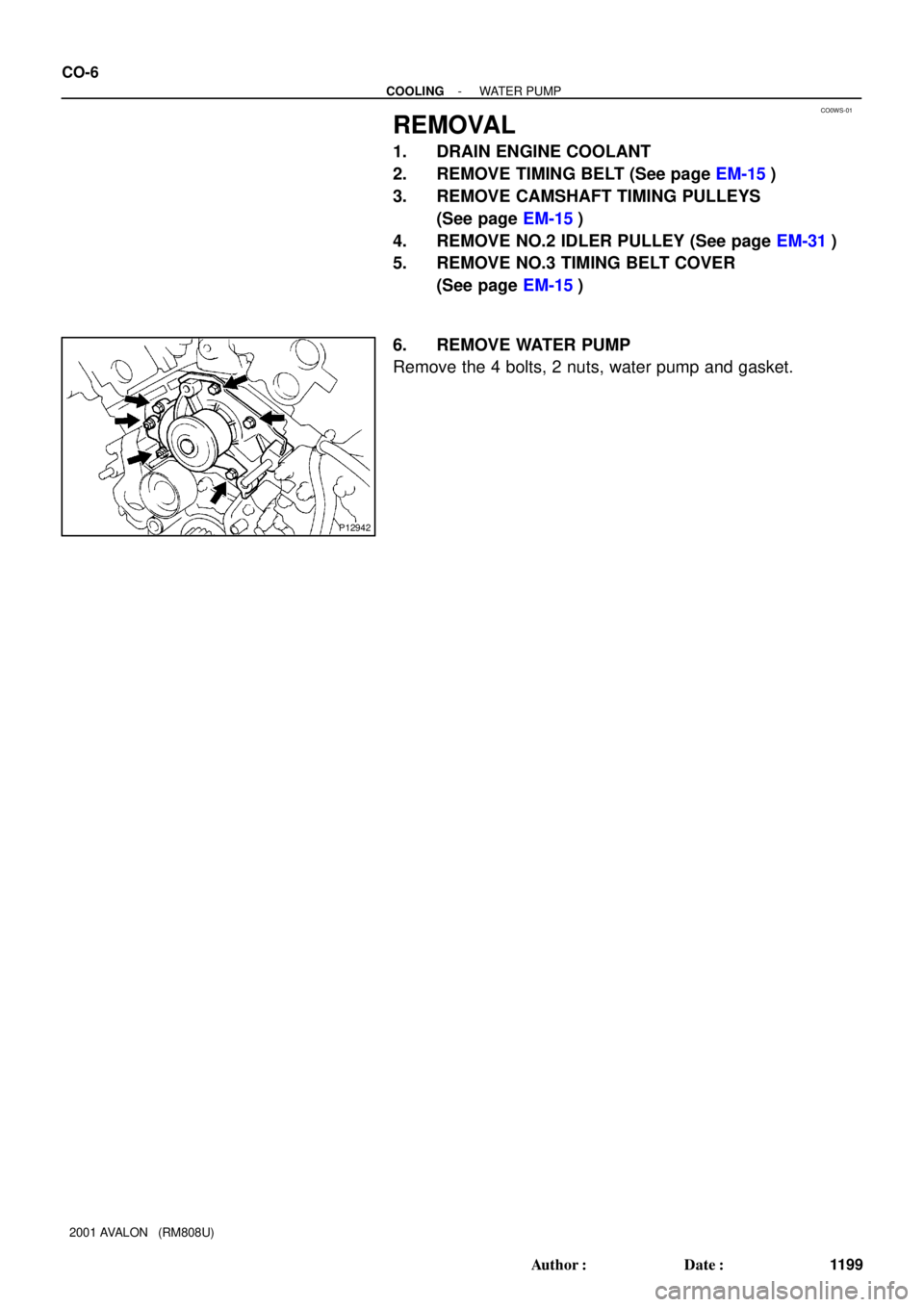
6. REMOVE WATER PUMP
Remove the 4 bolts, 2 nuts, water pump and gasket.
Page 1276 of 1897
 CONTROL SYSTEM
EC-9")
B08625AirDisconnect
Air Inlet
Line Hose
B01253
Pinch
Push
AA
Pinch
B08620
B08621
Purge Port
Vent Port
Cap EVAP Port
Air Drain Port
Air
- EMISSION CONTROLEVAPORATIVE EMISSION (EVAP) CONTROL SYSTEM
EC-9
1103 Author�: Date�:
2001 AVALON (RM808U)
7. CHECK AIR INLET LINE
(a) Disconnect the air inlet line hose from the charcoal canis-
ter.
(b) Check that there is ventilation in the air inlet line.
(c) Reconnect the air inlet line hose to the charcoal canister.
8. REMOVE CHARCOAL CANISTER ASSEMBLY
(a) Disconnect the VSV connector for the pressure switching
valve.
(b) Disconnect the vapor pressure sensor connector.
(c) Disconnect the fuel hose from the vapor pressure sensor.
(d) Disconnect the purge line hose, EVAP line hose and air
inlet line hose from the charcoal canister.
(e) Disconnect the vent line hose from the charcoal canister.
(1) Push the connector deep inside.
(2) Pinch portion A.
(3) Pull out the connector.
(f) Remove the 2 charcoal canister mounting bolts.
(g) Remove the vapor pressure sensor mounting bolt.
(h) Remove the charcoal canister assembly.
9. INSPECT CHARCOAL CANISTER
(a) Visually check the charcoal canister for cracks or dam-
age.
(b) Inspect the charcoal canister operation.
(1) Plug the vent port with the cap.
(2) While holding the purge port closed, blow air (1.76
kPa, 18 gf/cm
2, 0.26 psi) into the EVAP port and
check that air flows from the air drain port.
Page 1292 of 1897

13.")
P12389
SST
A05253
P18763
WaterSeal
Plate
Oil Filter
Union
12 mm
Hexagon
Wrench
Coolant
Drain
Union
A02010
P12508
EM-84
- ENGINE MECHANICALCYLINDER BLOCK
1068 Author�: Date�:
2001 AVALON (RM808U)
13. REMOVE KNOCK SENSORS
(a) Disconnect the 2 knock sensor connectors.
(b) Using SST, remove the 2 knock sensors.
SST 09816-30010
14. REMOVE WATER INLET HOUSING
(a) Remove the engine wire band.
(b) Disconnect the engine wire clamp from the bracket.
(c) Remove the 8 bolts, 2 nuts and water inlet housing.
15. REMOVE WATER PUMP (See page CO-6)
16. REMOVE NO.2 OIL PAN (See page LU-9)
17. REMOVE OIL STRAINER (See page LU-3)
18. REMOVE NO.1 OIL PAN (See page LU-3)
19. REMOVE OIL PUMP (See page LU-9)
20. REMOVE OIL FILTER (See page LU-3)
21. REMOVE OIL FILTER UNION
Using a 12 mm hexagon wrench, remove the oil filter union.
22. REMOVE WATER SEAL PLATE
Remove the 2 nuts and seal plate.
23. REMOVE ENGINE COOLANT DRAIN UNION
24. REMOVE CYLINDER BLOCK SIDE COVER
Remove the 3 bolts, 2 nuts, cylinder block side cover and gas-
ket.
25. REMOVE REAR OIL SEAL RETAINER
(a) Remove the 6 bolts.
(b) Using a screwdriver, remove the oil seal retainer by prying
the portions between the oil seal retainer and main bear-
ing cap.
Page 1369 of 1897

REMOVAL
1. REMOVE BATTERY AND TRAY
2. REMOVE HOOD
3. REMOVE ENGINE FENDER AP")
EM0ZL-02
A10518
5 mm
Hexagon
Wrench
A07300
EM-72
- ENGINE MECHANICALENGINE UNIT
1056 Author�: Date�:
2001 AVALON (RM808U)
REMOVAL
1. REMOVE BATTERY AND TRAY
2. REMOVE HOOD
3. REMOVE ENGINE FENDER APRON SEALS
4. DRAIN ENGINE COOLANT
5. DRAIN ENGINE OIL
6. REMOVE V-BANK COVER
(a) Using a 5 mm hexagon wrench, remove the 3 cap nuts.
(b) Loosen the V-bank cover fastener counterclockwise.
(c) Remove the V-bank cover.
7. DISCONNECT ACCELERATOR CABLE
8. REMOVE AIR CLEANER CAP ASSEMBLY AND AIR
CLEANER CASE
9. REMOVE CRUISE CONTROL ACTUATOR
10. REMOVE RADIATOR (See page CO-17)
11. REMOVE FRONT EXHAUST PIPE
(a) Remove the 2 bolts holding the support stay to the sup-
port bracket.
(b) Remove the 2 bolts and 2 compression springs holding
the front exhaust pipe to the center exhaust pipe.
(c) Remove the 4 nuts holding the front exhaust pipe to the
exhaust manifolds.
(d) Remove the front exhaust pipe and 3 gaskets.
12. DISCONNECT CONNECTORS, CABLE, CLAMPS AND
HOSES
(a) Remove the bolt and disconnect the ground strap from
the LH fender apron.
(b) Disconnect the 2 ground strap connectors from the RH
fender apron.
(c) Disconnect the ground cable from the A/T.
(d) Disconnect the engine wire protector clamp from the bat-
tery body bracket.
(e) Disconnect the engine wire clamp from the bracket on the
RH fender apron.
(f) Disconnect the brake booster vacuum hose from the
throttle body.
(g) Disconnect the engine coolant reservoir hose from the
water outlet.
(h) Disconnect the heater hose from the intake manifold.
(i) Disconnect the heater hose from the water inlet housing.
Page 1463 of 1897
LU0IB-01
P18778
Pivot
Bolt
Adjusting
Strut
Adjusting Bolt
B04135
P18801
- LUBRICATIONOIL PUMP
LU-9
1234 Author�: Date�:
2001 AVALON (RM808U)
REMOVAL
HINT:
When repairing the oil pump, the oil pan and strainer should be
removed and cleaned.
1. DRAIN ENGINE OIL
2. REMOVE RH FRONT WHEEL
3. REMOVE RH FENDER APRON SEAL
4. REMOVE FRONT EXHAUST PIPE
(See page EM-72)
5. REMOVE GENERATOR FROM ENGINE
(See page CH-6)
6. REMOVE A/C COMPRESSOR FROM ENGINE
(See page EM-72)
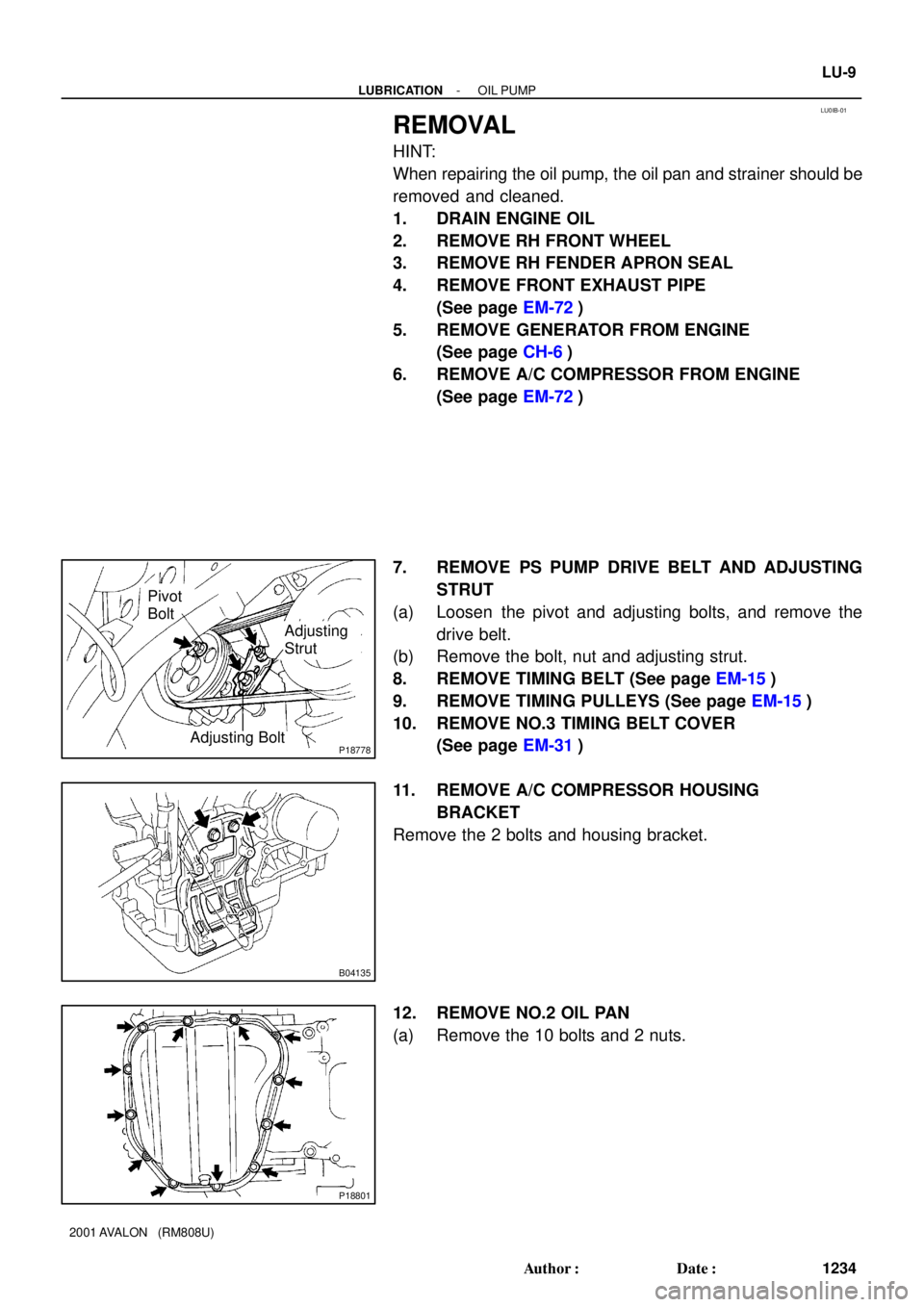
7. REMOVE PS PUMP DRIVE BELT AND ADJUSTING
STRUT
(a) Loosen the pivot and adjusting bolts, and remove the
drive belt.
(b) Remove the bolt, nut and adjusting strut.
8. REMOVE TIMING BELT (See page EM-15)
9. REMOVE TIMING PULLEYS (See page EM-15)
10. REMOVE NO.3 TIMING BELT COVER
(See page EM-31)
11. REMOVE A/C COMPRESSOR HOUSING
BRACKET
Remove the 2 bolts and housing bracket.
12. REMOVE NO.2 OIL PAN
(a) Remove the 10 bolts and 2 nuts.
Page 1551 of 1897

TORQUE SPECIFICATION
Part tightenedN´mkgf´cmft´lbf
Front side engine mounting insulator x Front")
SS0BM-04
- SERVICE SPECIFICATIONSAUTOMATIC TRANSAXLE
SS-25
141 Author�: Date�:
2001 AVALON (RM808U)
TORQUE SPECIFICATION
Part tightenedN´mkgf´cmft´lbf
Front side engine mounting insulator x Front frame assembly8082059
Rear engine mounting insulator x Front frame assembly6667048
LH transaxle mounting insulator x Front frame assembly8082059
Engine mounting insulator x Front frame assembly4849035
Transaxle x Engine 17 mm bolt
14 mm bolt66
48670
49048
35
Torque converter clutch x Drive plate4142030
Valve body x Transaxle case1111 08
Oil strainer x Valve body Bolt A
(See page AX-35) Bolt B10
11100
11 07
8
Oil pan x Transaxle case7.88069 in.´lbf
Oil pan drain plug4950036
Park/Neutral position switch x Transaxle case Bolt
Nut5.4
6.955
7048 in.´lbf
61 in.´lbf
Connector clamp x Valve body6.66758 in.´lbf
Manual valve body x Transaxle case1111 08
Line pressure test plug x Transaxle case7.58069 in.´lbf
Detent spring x Manual valve body1111 08
Oil pipe bracket x Transaxle case101007
Steering gear housing x Front frame assembly1811,850134
Stabilizer bar bracket x Front frame assembly1919514
Stabilizer bar link x Stabilizer bar3940029
Lower suspension arm x Lower ball joint1271,30094
Tie rod end x Steering knuckle4950036
Drive shaft lock nut2943,000217
Direct clutch speed sensor x Transaxle case1111 08
Exhaust manifold bracket x Transaxle case2020015
Exhaust manifold plate2020015
Front frame assembly x Body 19 mm bolt
14 mm bolt
Nut181
32
361,850
330
370134
24
27
Front exhaust pipe x Exhaust center pipe4344032
Exhaust manifold x Front exhaust pipe6263046
Exhaust front pipe support stay x Exhaust front pipe support bracket3333024
Starter x Torque converter clutch housing3940029
Transaxle control shaft lever x Park/neutral position switch1515011
Throttle cable adjusting nut1515011
Drive plate x Crankshaft8385061
Shift control cable x Transaxle control shaft lever1515011
Throttle cable retaining plate set bolt5.45548 in.´lbf
Shift solenoid valve No. 1, No. 2, SL, SLN x Valve body6.66758 in.´lbf
Front wheel nut1031,05076
Exhaust front pipe support bracket x Body2121015
PS reservoir pipe x Front frame101007
Page 1568 of 1897
 Engine coolant drain union x Cylinder block
3940029
Water seal plate x Cylinder block1818013
Oil filter union")
SS-10
- SERVICE SPECIFICATIONSENGINE MECHANICAL
126 Author�: Date�:
2001 AVALON (RM808U) Engine coolant drain union x Cylinder block
3940029
Water seal plate x Cylinder block1818013
Oil filter union x Cylinder block3031022
Water inlet housing x Cylinder block88069 in.´lbf
Knock sensor x Cylinder block3940029
No.2 idler pulley bracket x Cylinder block2829021
A/C compressor housing bracket x Cylinder block2525018
Generator bracket x Cylinder block4344032
Drive plate x Crankshaft8385061
Transaxle x Engine6465047
No.1 oil pan x Transaxle37.238027
Drive plate x Torque convertor clutch4142030
Flywheel housing under cover x Transaxle7.88069 in.´lbf
Rear engine mounting insulator x Cylinder block6465047
Front engine mounting insulator x Cylinder block6465047
Engine moving control rod x RH engine mounting bracket6465047
Engine moving control rod x RH fender apron6465047
RH engine mounting stay x Water outlet3232023
RH engine mounting stay x Engine moving control rod3232023
RH engine mounting stay x No.2 RH engine mounting bracket3232023
Front engine mounting insulator x Front frame Silver color bolt
Green color bolt44
66450
67032
49
Engine mounting absorber x Front frame4849035
Engine mounting absorber x Transaxle4849035
Rear engine mounting insulator x Front frame6667048
LH engine mounting insulator x Transaxle6465047
PS pump x PS pump bracket4344031
A/C compressor x Housing bracket25.526019
A/C compressor x No.1 oil pan25.526019
Generator adjusting bar x Drive belt adjusting bar bracket1818513
Fuel inlet hose x Fuel filter2930021
Front exhaust pipe support bracket x No.1 oil pan20.621015
Front exhaust pipe x Exhaust manifold6263046
Front exhaust pipe x Center exhaust pipe5657041
Center exhaust pipe x Tailpipe5657041
Front exhaust pipe bracket x Sub frame3333024
Front exhaust pipe support bracket x Front exhaust pipe stay3333024