Page 270 of 1897

I13309
9 62
3
7
I13310
9 62
3
7
I13311
8 62
7
1
I13312
8 62
7
1
I07530
SW1 SW2 SET Switch
BE-1 18
- BODY ELECTRICALPOWER MIRROR CONTROL SYSTEM
1722 Author�: Date�:
2001 AVALON (RM808U)
10. w/ Driving position memory:
INSPECT MIRROR POSITION SENSORS OPERATION
HINT:
Strip off the vinyl tape of the connector and remove terminals
2, 3, 6, 7 and 9 from the connector housing.
(a) Connect a series of three 1.5 V dry cell batteries.
(b) Connect the positive (+) lead from the dry cell batteries to
terminal 7 and the negative (-) lead to terminal 6.
(c) Connect the positive (+) lead from the voltmeter to termi-
nal 9 and the negative (-) lead to terminal 6.
(d) Apply Battery voltage to terminals 2 and 3, then check
that the voltage gradually changes according to the table
below while the mirror moves between the uppermost
position and lowermost position.
Mirror
positionLowermostMirror
positionUppermost
Voltage2.8 - 5.0Changes
gradually0 - 1.8
If voltage value is not as specified, replace the motor assembly.
(e) Disconnect the 4 leads of the battery and voltmeter.
(f) Connect the positive (+) lead from the voltmeter to termi-
nal 8 and negative (-) lead to terminal 6.
(g) Apply Battery voltage to terminals 2 and 1, then inspect
that the voltage gradually changes according to the table
below while the mirror moves between the left-most posi-
tion and right-most position.
Mirror
positionLeft-mostMirror
positionRight-most
Voltage
LEFT2.8 - 5.0Changes
gradually0 - 1.8
Voltage
RIGHT0 - 1.8Changes
gradually2.8 -5.0
If voltage value is not as specified, replace the motor assembly.
11. INSPECT DRIVING POSITION MEMORY AND RE-
TURN SWITCH CONTINUITY
Switch positionTester connectionSpecified condition
SET switch ON3 - 4Continuity
Return SW1 ON2 - 3Continuity
Return SW2 ON1 - 3Continuity
If continuity is not as specified, replace the switch.
Page 621 of 1897
F09800
ABS Actuator
and ECU
A714
STP Driver Side J/B
BatteryJ/B No. 4
S4
Stop Light SwitchR7
Rear Combination
Light LH
G-W
14
IE1 G-W
G-W
J/B No. 3
16
4D 16
4F G-W3
3F 3
3C 5
1B 3
1D
4
1E
12R
11
1D STOP
FL Block
FL MAIN
L5
Light Failure
SensorStop
J12
J/C 1
1G W
1
F101
F6B5
IK1
7
Stop
36
G-R
B BBW-B
C
C
W-B
R8
Rear Combination
Light RH
36
G-R
G-R 2
1R-WH11
High Mounted
Stop Light
21
W-BC
C
W-B
BM ALTG-W G-W
G-W Driver Side J/B
J12
J/C DI-234
- DIAGNOSTICSANTI-LOCK BRAKE SYSTEM WITH ELECTRONIC
BRAKE FORCE DISTRIBUTION (EBD)
390 Author�: Date�:
2001 AVALON (RM808U)
DTC 58 Stop Light Switch Circuit
CIRCUIT DESCRIPTION
DTC No.DTC Detecting ConditionTrouble Area
58
Stop light switch circuit is open, and stop light switch volt-
age is in the level between 55 % and 75 % of the battery
voltage.�Stop light switch
�Stop light switch circuit
WIRING DIAGRAM
DI6NI-02
Page 870 of 1897
I13611
Cruise Control ECU
9
B
Y-R
IG B 3 1
4IG1 RELAY
2
AM1 ECU-IG NO. 2
5 5
B-L
ALT FL Block
F6
B
FL MAIN
BatteryW-BW-B 1
2G
F8
W-B AA
J5
J/C 1 F101 1
1G
3
1B
1
2H13
1B
4
1C2
3C2
3D
7
IF1
7
3A20
3BGND
1W-B16 W-B WY-R
W-R42
I15Ignition Switch
C15
W-L
W-L
B-LIG1 AM1
2
1J/B No. 3
Driver Side J/B
Engine Room J/B
Engine Room R/B No. 5
J/B No. 3
- DIAGNOSTICSCRUISE CONTROL SYSTEM
DI-587
743 Author�: Date�:
2001 AVALON (RM808U)
ECU Power Source Circuit
CIRCUIT DESCRIPTION
The ECU power source supplies power to the actuator and sensors, etc, when terminal GND and the cruise
control ECU case are grounded.
WIRING DIAGRAM
DI08X-15
Page 1022 of 1897

DI-54
- DIAGNOSTICSENGINE
210 Author�: Date�:
HINT:
�When the DTC P0171 or P0174 is recorded, the actual air-fuel ratio is on the lean side. When DTC
P0172 or P0175 is recorded, the actual air-fuel ratio is on the rich side.
�If the vehicle runs out of fuel, the air-fuel ratio is lean and DTC P0171 or P0174 is recorded. The MIL
then comes on.
�If the total of the short-term fuel trim value and the long-term fuel trim value is within + 35 % (80°C
(176°F) or more), the system is functioning normally.
�The A/F sensors (bank 1, 2 sensor 1) output voltage and the short-term fuel trim value can be read
using the OBD II scan tool or hand-held tester.
�The ECM controls the voltage of AFR+, AFL+, AFR- and AFL- terminals of ECM to the fixed voltage.
Therefore, it is impossible to confirm the A/F sensor output voltage without OBD II scan tool or hand-
held tester.
�OBD II scan tool (excluding hand-held tester) displays the one fifth of the A/F sensors (bank 1, 2 sen-
sor 1) output voltage which is displayed on the hand-held tester.
WIRING DIAGRAM
Refer to DTC P0125 on page DI-43.
INSPECTION PROCEDURE
HINT:
Read freeze frame data using TOYOTA hand-held tester or OBD II scan tool. Because freeze frame records
the engine conditions when the malfunction is detected. When troubleshooting, it is useful for determining
whether the vehicle was running or stopped, the engine was warmed up or not, the air-fuel ratio was lean
or rich, etc. at the time of the malfunction.
1 Check air induction system (See page SF-1).
NG Repair or replace.
OK
2 Check injector injection (See page SF-23).
NG Replace injector.
OK
Page 1084 of 1897
- DIAGNOSTICSPOWER SEAT CONTROL SYSTEM (w/ Driving Position
Memory)DI-507
663 Author�: Date�:
2001 AVALON (RM808U)
2 Check harness and connectors between Seat Position Control ECU and position
sensors (See page IN-30).
NG Repair or replace harness or connectors.
OK
Check and replace Seat Position Control
ECU.
Page 1085 of 1897
I13624
SSRR
PVCC
SSFV SSRS
SSRL L-BL
R
L-W53
4 16
17Power Seat ECU
1 2
1 2
1 2
1 2
3 3 3 3
BR
BR
BR B
BB B
BR J14
J/C
9
9
BR
BR A
AJ3
J/C
IHP21
P21
P21
P21
P21 L-R BR
P30
P29
P32
P31
Power Seat
Position Sensor
Reclining Control
Front Vertical Control
Rear Vertical Control Slide Control
IA1 BC1
BR
J/CJ14
A
A
A A R
R
R
R DI-504
- DIAGNOSTICSPOWER SEAT CONTROL SYSTEM (w/ Driving Position
Memory)
660 Author�: Date�:
2001 AVALON (RM808U)
Position Sensor Power Source Circuit
CIRCUIT DESCRIPTION
This circuit provides power to the slide, front vertical and reclining position sensors.
WIRING DIAGRAM
DI0G6-09
Page 1292 of 1897

P12389
SST
A05253
P18763
WaterSeal
Plate
Oil Filter
Union
12 mm
Hexagon
Wrench
Coolant
Drain
Union
A02010
P12508
EM-84
- ENGINE MECHANICALCYLINDER BLOCK
1068 Author�: Date�:
2001 AVALON (RM808U)
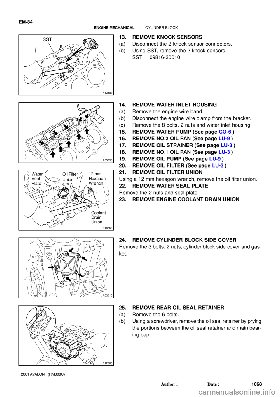
13. REMOVE KNOCK SENSORS
(a) Disconnect the 2 knock sensor connectors.
(b) Using SST, remove the 2 knock sensors.
SST 09816-30010
14. REMOVE WATER INLET HOUSING
(a) Remove the engine wire band.
(b) Disconnect the engine wire clamp from the bracket.
(c) Remove the 8 bolts, 2 nuts and water inlet housing.
15. REMOVE WATER PUMP (See page CO-6)
16. REMOVE NO.2 OIL PAN (See page LU-9)
17. REMOVE OIL STRAINER (See page LU-3)
18. REMOVE NO.1 OIL PAN (See page LU-3)
19. REMOVE OIL PUMP (See page LU-9)
20. REMOVE OIL FILTER (See page LU-3)
21. REMOVE OIL FILTER UNION
Using a 12 mm hexagon wrench, remove the oil filter union.
22. REMOVE WATER SEAL PLATE
Remove the 2 nuts and seal plate.
23. REMOVE ENGINE COOLANT DRAIN UNION
24. REMOVE CYLINDER BLOCK SIDE COVER
Remove the 3 bolts, 2 nuts, cylinder block side cover and gas-
ket.
25. REMOVE REAR OIL SEAL RETAINER
(a) Remove the 6 bolts.
(b) Using a screwdriver, remove the oil seal retainer by prying
the portions between the oil seal retainer and main bear-
ing cap.
Page 1314 of 1897

P12909
Seal Width 3 - 5 mm
A05253410
2
5
7
93
1
6
8
P12389
SST EM-108
- ENGINE MECHANICALCYLINDER BLOCK
1092 Author�: Date�:
2001 AVALON (RM808U)
�Using a non-residue solvent, clean both sealing
surfaces.
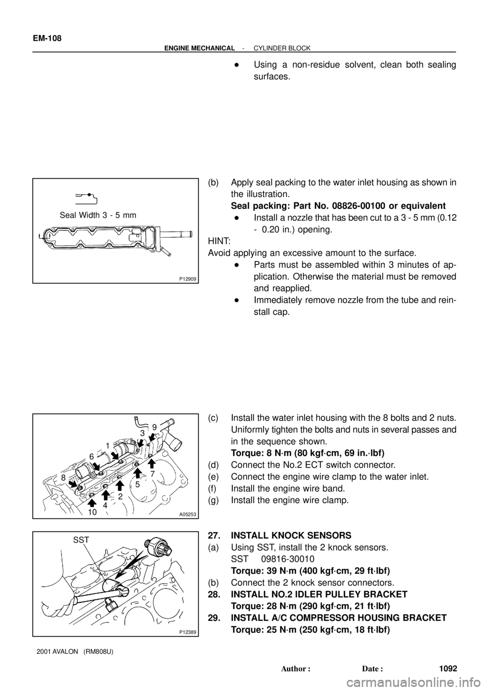
(b) Apply seal packing to the water inlet housing as shown in
the illustration.
Seal packing: Part No. 08826-00100 or equivalent
�Install a nozzle that has been cut to a 3 - 5 mm (0.12
- 0.20 in.) opening.
HINT:
Avoid applying an excessive amount to the surface.
�Parts must be assembled within 3 minutes of ap-
plication. Otherwise the material must be removed
and reapplied.
�Immediately remove nozzle from the tube and rein-
stall cap.
(c) Install the water inlet housing with the 8 bolts and 2 nuts.
Uniformly tighten the bolts and nuts in several passes and
in the sequence shown.
Torque: 8 N´m (80 kgf´cm, 69 in.´lbf)
(d) Connect the No.2 ECT switch connector.
(e) Connect the engine wire clamp to the water inlet.
(f) Install the engine wire band.
(g) Install the engine wire clamp.
27. INSTALL KNOCK SENSORS
(a) Using SST, install the 2 knock sensors.
SST 09816-30010
Torque: 39 N´m (400 kgf´cm, 29 ft´lbf)
(b) Connect the 2 knock sensor connectors.
28. INSTALL NO.2 IDLER PULLEY BRACKET
Torque: 28 N´m (290 kgf´cm, 21 ft´lbf)
29. INSTALL A/C COMPRESSOR HOUSING BRACKET
Torque: 25 N´m (250 kgf´cm, 18 ft´lbf)