Page 34 of 1897
AC2GS-01
I12986
- AIR CONDITIONINGAIR REFINER FILTER
AC-89
2011 Author�: Date�:
2001 AVALON (RM808U)
AIR REFINER FILTER
REPLACEMENT
1. REMOVE GLOVE COMPARTMENT PARTS
(See page BO-90)
2. REMOVE AIR REFINER FILTER
(a) Remove the filter cover.
(b) Pull out the filter.
(c) Remove the filter from the frame.
3. INSTALL AIR REFINER FILTER
(a) Install the filter to the frame.
(b) Install the filter.
(c) Install the filter cover.
4. INSTALL GLOVE COMPARTMENT PARTS
(See page BO-97)
Page 39 of 1897
I12954
Auto A/C models:
Air Refiner FilterBlower Unit Case
Air Inlet Servomotor
Blower Motor
Wire Harness
Auto A/C:
Blower Motor
Linear ControllerManual A/C:
Blower Resister AC-36
- AIR CONDITIONINGBLOWER UNIT
1958 Author�: Date�:
2001 AVALON (RM808U)
Page 40 of 1897
AC2G2-01
I12927
I12985
AC-38
- AIR CONDITIONINGBLOWER UNIT
1960 Author�: Date�:
2001 AVALON (RM808U)
DISASSEMBLY
1. REMOVE AIR REFINER FILTER
(a) Release the 2 claws and remove the cover.
(b) Pull out the air refiner filter.
(c) Remove the filter from filter case.
2. REMOVE BLOWER MOTOR
Remove the 3 screws and motor.
3. REMOVE AIR INLET SERVOMOTOR
Remove the 3 screws and servomotor.
Page 56 of 1897
AC28I-02
I12949I12950
I12965
N´m (kgf´cm, ft´lbf) : Specified torque
� Non-reusable part
Compressor oil ND-OIL 8 or equivalent
5.4 (55, 48 in.´lbf)
5.4 (55, 48 in.´lbf)
Discharge Hose
Liquid Tube� O-ringRadiator Upper SupportCondenser
Radiator Upper Support
Condenser
Dryer
Filter
Cap
12.3 (125, 9)
� O-ring
AC-52
- AIR CONDITIONINGCONDENSER
1974 Author�: Date�:
2001 AVALON (RM808U)
COMPONENTS
Page 60 of 1897
AC28K-02
I10090
10 mm (0.39 in.)
Hexagon
Wrench
Modulator
I10092
I10093
2 Layered
Part
I10091
Protrusion
I10094
AC-54
- AIR CONDITIONINGCONDENSER
1976 Author�: Date�:
2001 AVALON (RM808U)
REPLACEMENT
REPLACE DRIER FROM MODULATOR
(a) Using a hexagon wrench (10 mm, 0.39 in.), remove the
cap from the modulator.
(b) Remove the filter from the modulator.
(c) Using pliers, remove the drier.
(d) Insert a new drier into the modulator.
NOTICE:
�Do not remove the drier from a vinyl bag until insert-
ing it into the modulator.
�Install the drier with its 2 layered part faced upward to
the modulator.
(e) Insert the filter into the modulator.
NOTICE:
Install the filter with its protrusion faced downward to the
modulator.
(f) Install the cap to the modulator.
(1) Apply compressor oil to the O-rings and screw part
of the cap.
Compressor oil: ND-OIL 8 or equivalent
(2) Using a hexagon wrench (10 mm, 0.39 in.), install
the caps.
Torque: 12.3 N´m (125 kgf´cm, 9 ft´lbf)
Page 175 of 1897

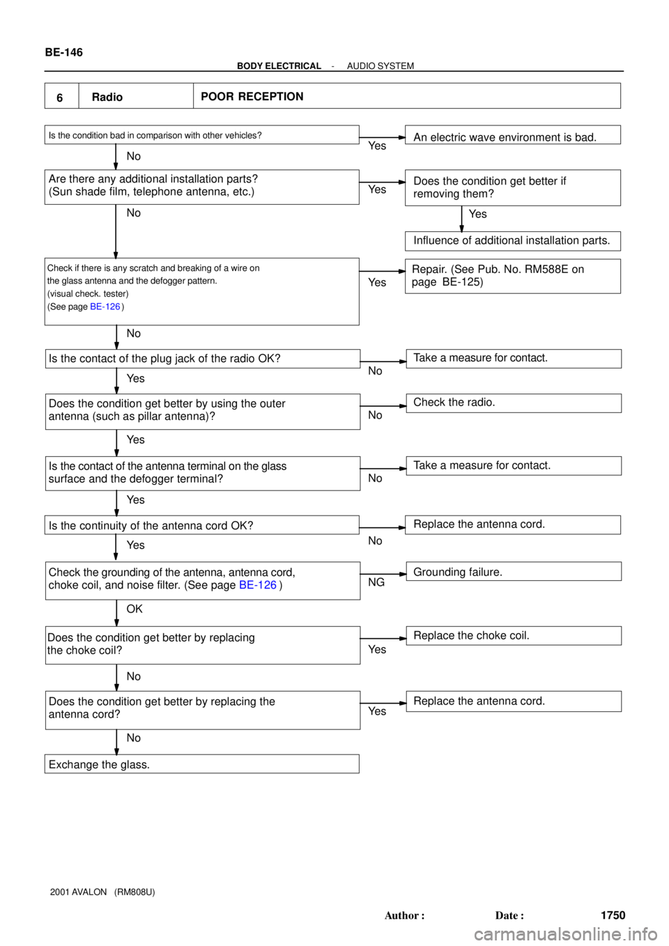
6RadioPOOR RECEPTION
Is the condition bad in comparison with other vehicles?
Are there any additional installation parts?
(Sun shade film, telephone antenna, etc.)
Check if there is any scratch and breaking of a wire on
the glass antenna and the defogger pattern.
(visual check. tester)
(See page BE-126)
Is the contact of the plug jack of the radio OK?
Does the condition get better by using the outer
antenna (such as pillar antenna)?
Is the contact of the antenna terminal on the glass
surface and the defogger terminal?
Is the continuity of the antenna cord OK?
Check the grounding of the antenna, antenna cord,
choke coil, and noise filter. (See page BE-126)
Does the condition get better by replacing
the choke coil?
Does the condition get better by replacing the
antenna cord?Take a measure for contact. An electric wave environment is bad.
Does the condition get better if
removing them?
Influence of additional installation parts.
Repair. (See Pub. No. RM588E on
page BE-125)
Check the radio.
Take a measure for contact.
Grounding failure. Replace the antenna cord.
Replace the choke coil.
Replace the antenna cord. Ye s
No
Exchange the glass.Ye s
Ye s
Ye s
Ye s
Ye s
Ye s
Ye s
Ye s No
No
No
NoNo
No
No
No
NG
OK
Ye s BE-146
- BODY ELECTRICALAUDIO SYSTEM
1750 Author�: Date�:
2001 AVALON (RM808U)
Page 905 of 1897

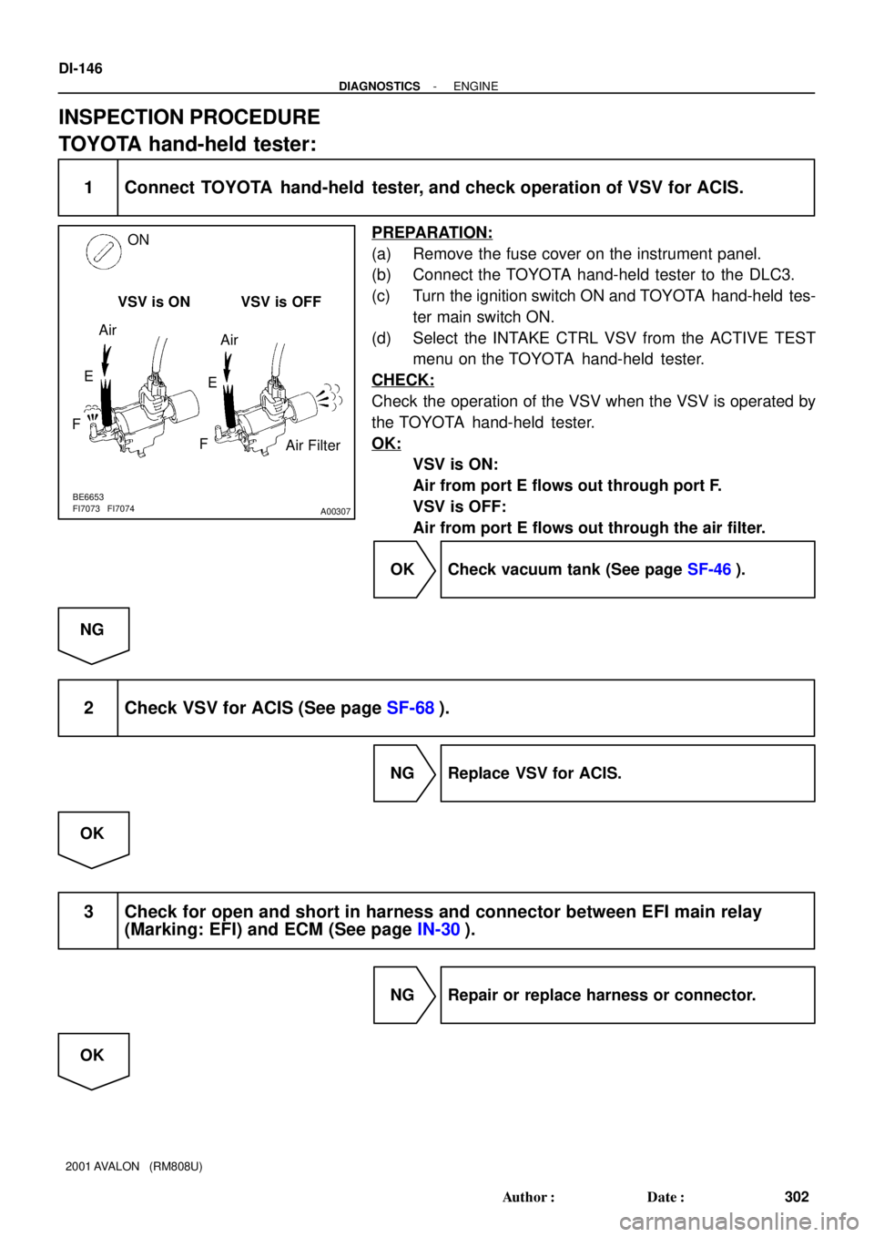
A00307
ON
VSV is ON VSV is OFF
Air Filter Air
Air
E
FE
F
BE6653
FI7073 FI7074
DI-146
- DIAGNOSTICSENGINE
302 Author�: Date�:
2001 AVALON (RM808U)
INSPECTION PROCEDURE
TOYOTA hand-held tester:
1 Connect TOYOTA hand-held tester, and check operation of VSV for ACIS.
PREPARATION:
(a) Remove the fuse cover on the instrument panel.
(b) Connect the TOYOTA hand-held tester to the DLC3.
(c) Turn the ignition switch ON and TOYOTA hand-held tes-
ter main switch ON.
(d) Select the INTAKE CTRL VSV from the ACTIVE TEST
menu on the TOYOTA hand-held tester.
CHECK:
Check the operation of the VSV when the VSV is operated by
the TOYOTA hand-held tester.
OK:
VSV is ON:
Air from port E flows out through port F.
VSV is OFF:
Air from port E flows out through the air filter.
OK Check vacuum tank (See page SF-46).
NG
2 Check VSV for ACIS (See page SF-68).
NG Replace VSV for ACIS.
OK
3 Check for open and short in harness and connector between EFI main relay
(Marking: EFI) and ECM (See page IN-30).
NG Repair or replace harness or connector.
OK
Page 930 of 1897
DI-46
- DIAGNOSTICSENGINE
202 Author�: Date�:
2001 AVALON (RM808U)
3 Check for open and short in harness and connector between ECM and A/F sen-
sor (bank 1, 2 sensor 1) (See page IN-30).
NG Repair or replace harness or connector.
OK
4 Check resistance of A/F sensor heater (bank 1, 2 sensor 1) (See page SF-79).
NG Replace A/F sensor.
OK
5 Check air induction system (See page SF-1).
NG Repair or replace.
OK
6 Check fuel pressure (See page SF-6).
NG Check and repair fuel pump, pressure regulator,
fuel pipe line and filter (See page SF-1).
OK
7 Check injector injection (See page SF-23).
NG Replace injector.
OK