Page 1580 of 1897
SS0EK-02
- SERVICE SPECIFICATIONSSFI
SS-13
129 Author�: Date�:
2001 AVALON (RM808U)
TORQUE SPECIFICATION
Part tightenedN´mkgf´cmft´lbf
Fuel line (Union bolt type)2930021
Fuel line (Flare nut type) using SST2828521
Fuel pump assembly x Fuel tank44035 in.´lbf
Fuel filter x Fuel pump bracket2.02017 in.´lbf
Fuel pressure regulator x Fuel pump bracket2.02017 in.´lbf
Delivery pipe x Intake manifold101007
No.1 fuel pipe x Intake manifold19.520014
Fuel tank band x Body3940029
Throttle body x Throttle body bracket19.520014
Throttle body x Air intake chamber19.520014
Throttle body x No.1 intake air control valve6.97061 in.´lbf
Camshaft timing oil control valve x Cylinder head7.58066 in.´lbf
No.2 intake air control valve x Air intake chamber14.514510
ECT sensor x Water outlet2020014
Knock sensor x Cylinder block3940029
A/F sensor x Exhaust manifold4444032
Heated oxygen sensor x Exhaust pipe4444031
Page 1636 of 1897

(m) Tighten the 4 bolts holding the delivery pipes to the intake
manifold.
Torq")
B01020
B06618
Align
B09079
B09076
Fuel Hose
Clamp
B06613
SF-26
- SFIINJECTOR
1135 Author�: Date�:
2001 AVALON (RM808U)
(m) Tighten the 4 bolts holding the delivery pipes to the intake
manifold.
Torque: 10 N´m (100 kgf´cm, 7 ft´lbf)
(n) Tighten the bolt holding the No.1 fuel pipe to the intake
manifold.
Torque: 19.5 N´m (200 kgf´cm, 14 ft´lbf)
2. CONNECT NO.1 FUEL PIPE
(a) Align the alignment marks (white paint) on the No.1 fuel
pipe.
(b) Connect the No.1 fuel pipe (fuel tube connector) to the
fuel filter.
CAUTION:
Perform connecting operations of the fuel tube connector
(quick type) after observing the precautions.
(c) Surely install the fuel hose clamp to the fuel filter with
ºclickº sound.
(d) After installing the clamp, check that the clamp is fixed by
pulling up the clamp.
3. INSTALL AIR ASSIST HOSES AND PIPE
4. CONNECT INJECTOR CONNECTORS
5. INSTALL AIR INTAKE CHAMBER ASSEMBLY
(See page EM-59)
6. INSTALL AIR CLEANER HOSE WITH RESONATOR
7. INSTALL V-BANK COVER
(a) Using 5 mm hexagon wrench, install the V-bank cover
with the 3 cap nuts.
(b) Press down the V-bank cover fastener.
8. CHECK FOR FUEL LEAKS
Page 1638 of 1897
SF0ZR-02
A10518
5 mm
Hexagon
Wrench
S04505
B06613
B09076
Fuel Hose
Clamp
B09077
- SFIINJECTOR
SF-21
1130 Author�: Date�:
2001 AVALON (RM808U)
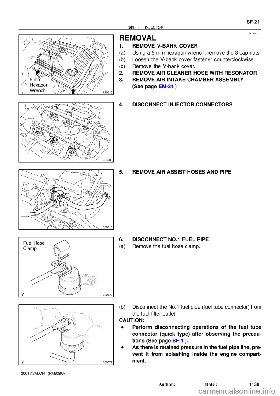
REMOVAL
1. REMOVE V-BANK COVER
(a) Using a 5 mm hexagon wrench, remove the 3 cap nuts.
(b) Loosen the V-bank cover fastener counterclockwise.
(c) Remove the V-bank cover.
2. REMOVE AIR CLEANER HOSE WITH RESONATOR
3. REMOVE AIR INTAKE CHAMBER ASSEMBLY
(See page EM-31)
4. DISCONNECT INJECTOR CONNECTORS
5. REMOVE AIR ASSIST HOSES AND PIPE
6. DISCONNECT NO.1 FUEL PIPE
(a) Remove the fuel hose clamp.
(b) Disconnect the No.1 fuel pipe (fuel tube connector) from
the fuel filter outlet.
CAUTION:
�Perform disconnecting operations of the fuel tube
connector (quick type) after observing the precau-
tions (See page SF-1).
�As there is retained pressure in the fuel pipe line, pre-
vent it from splashing inside the engine compart-
ment.
Page 1663 of 1897

1177 Author�: Date�:
2001 AVAL")
SF06N-03
S04525
Ohmmeter
Continuity
S04524
Ohmmeter
No Continuity
FI6393
Air
E
Filter
S04523
Air
E
F
Battery SF-68
- SFIVSV FOR ACOUSTIC CONTROL INDUCTION
SYSTEM (ACIS)
1177 Author�: Date�:
2001 AVALON (RM808U)
INSPECTION
1. REMOVE V- BANK COVER, AND EMISSION CON-
TROL VALVE SET
2. REMOVE VSV
(a) Disconnect the 2 vacuum hoses from the VSV.
(b) Remove the screw and VSV.
3. INSPECT VSV FOR OPEN CIRCUIT
Using an ohmmeter, check that there is continuity between
each terminals.
Resistance: 33 - 39 W at 20°C (68°F)
If there is no continuity, replace the VSV.
4. INSPECT VSV FOR GROUND
Using an ohmmeter, check that there is no continuity between
each terminal and the body.
If there is continuity, replace the VSV.
5. INSPECT VSV OPERATION
(a) Check that air flows from port E to the filter.
(b) Apply battery voltage across the terminals.
(c) Check that air flows from port E to port F.
If operation is not as specified, replace the VSV.
6. REINSTALL VSV
(a) Install the VSV with the screw.
(b) Connect the 2 vacuum to the VSV.
7. REINSTALL EMISSION CONTROL VALVE SET
8. REINSTALL V-BANK COVER