Page 941 of 1897
FI6588
FI6538
A00064
10 V
/Division10 V
/Division
GND GND
100 msec./Division (Idling)1 msec./Division (Idling)
Injection duration
(Magnification) Injector Signal Waveform
DI-62
- DIAGNOSTICSENGINE
218 Author�: Date�:
2001 AVALON (RM808U)
Reference: INSPECTION USING OSCILLOSCOPE
With the engine idling, check the waveform between terminals #10 - #60 and E01 of the ECM connector.
HINT:
The correct waveform is as shown.
OK Go to step 5.
NG
4 Check resistance of injector of misfiring cylinder (See page SF-19).
NG Replace injector.
OK
Check for open and short in harness and con-
nector between injector and ECM (See page
IN-30).
5 Check fuel pressure (See page SF-6).
NG Check and repair fuel pump, fuel pipe line and
filter (See page SF-1).
Page 988 of 1897
- DIAGNOSTICSENGINE
DI-109
265 Author�: Date�:
2001 AVALON (RM808U)
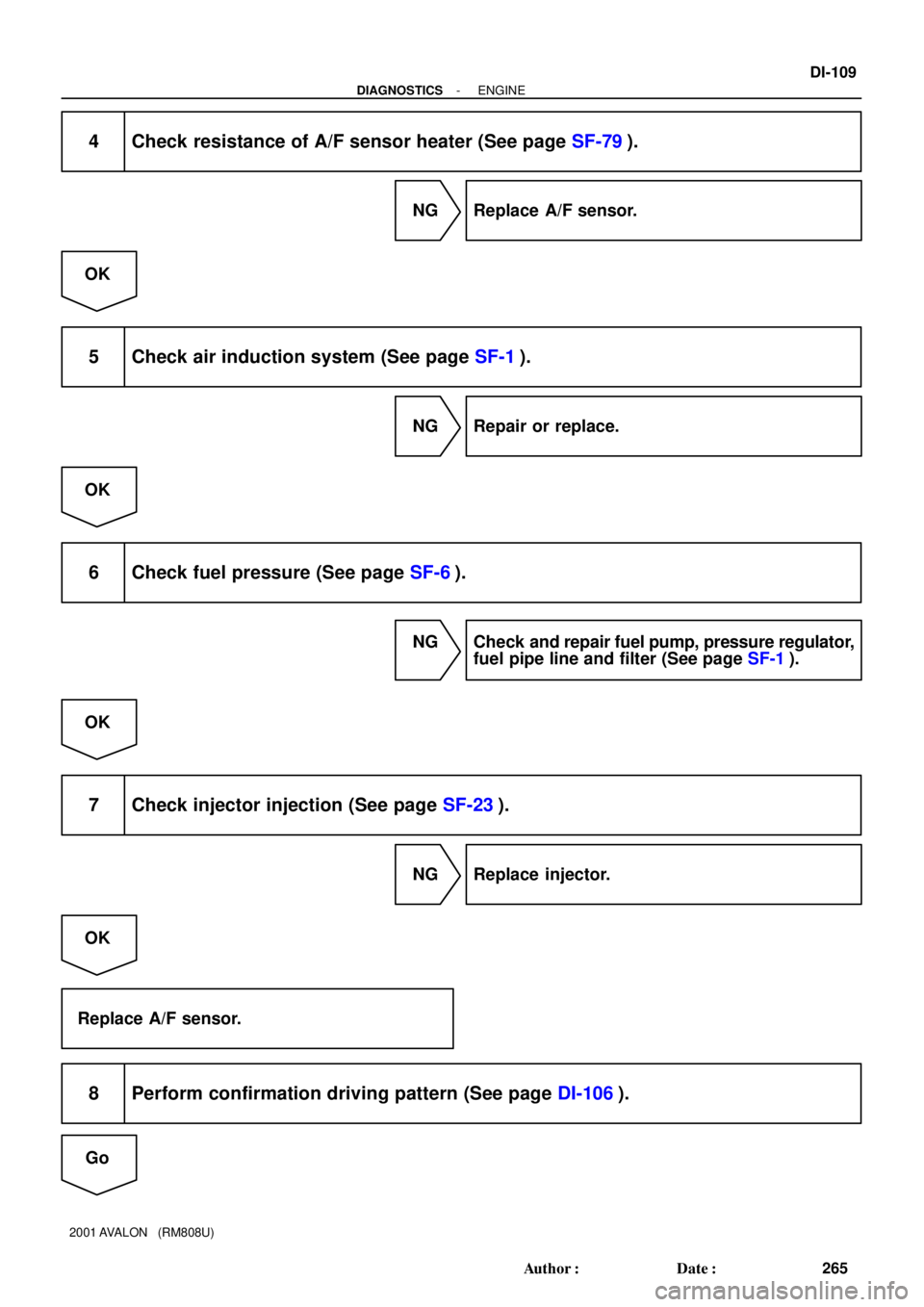
4 Check resistance of A/F sensor heater (See page SF-79).
NG Replace A/F sensor.
OK
5 Check air induction system (See page SF-1).
NG Repair or replace.
OK
6 Check fuel pressure (See page SF-6).
NG Check and repair fuel pump, pressure regulator,
fuel pipe line and filter (See page SF-1).
OK
7 Check injector injection (See page SF-23).
NG Replace injector.
OK
Replace A/F sensor.
8 Perform confirmation driving pattern (See page DI-106).
Go
Page 992 of 1897
- DIAGNOSTICSENGINE
DI-1 13
269 Author�: Date�:
2001 AVALON (RM808U)
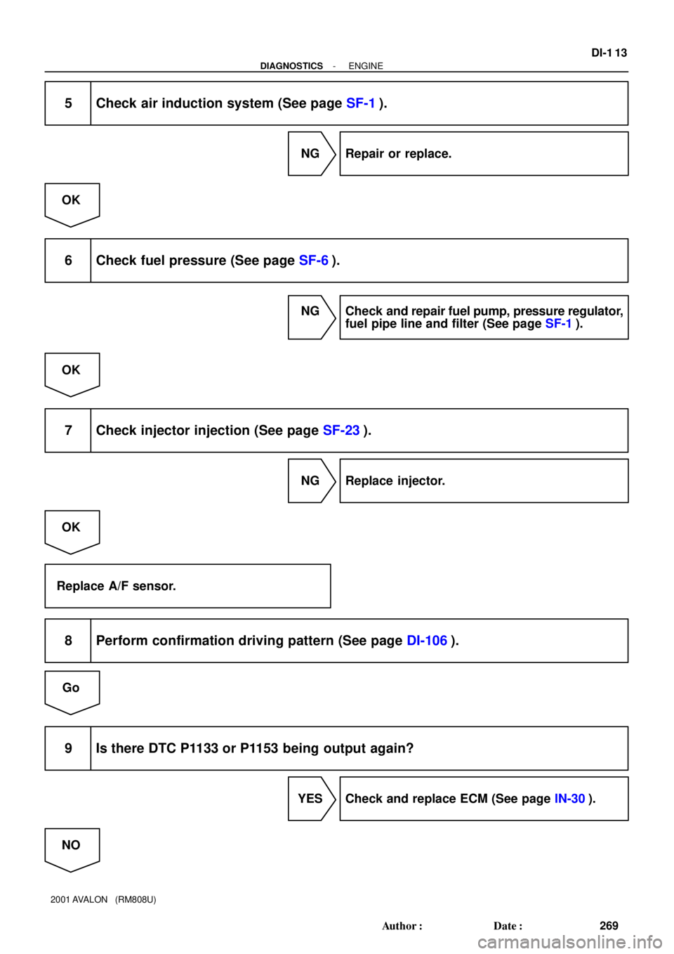
5 Check air induction system (See page SF-1).
NG Repair or replace.
OK
6 Check fuel pressure (See page SF-6).
NG Check and repair fuel pump, pressure regulator,
fuel pipe line and filter (See page SF-1).
OK
7 Check injector injection (See page SF-23).
NG Replace injector.
OK
Replace A/F sensor.
8 Perform confirmation driving pattern (See page DI-106).
Go
9 Is there DTC P1133 or P1153 being output again?
YES Check and replace ECM (See page IN-30).
NO
Page 997 of 1897

A11669
14
3 2
B-R
L LG-B
L-Y
LG 1
4
2
43
21
43
21
43
21
43
2
Ignition Coil
with Igniter
No.2
No.3
No.4
No.5
No.6
Noise
Filter B-Y W-BB-W
GR
13 No.1B-W
B-W B-W B-W
B-WB-Y
B-Y B-Y B-Y B-Y B-Y
W-B
W-B
W-B
W-B W-B
1
B-W
B-WW-B
B-W
B-W
B-WW-B W-B W-B
B-W
W-BIGT1
IGF IGT2
IGT3
IGT4
IGT5
IGT6 11
12
13
14
15
16
25 E4
E4
E4
E4
E4
E4
E4ECM
Battery
EC ED
115
2B
B-O
2F 1C28
3
IG Switch72
14 IG2 Reray
2G
2C 2CIG2
AM2 72
1J B-O
7
6W-R
W-R4
IF1Engine Room J/B
Driver Side J/BB
Fusible
Link
Block
FL
Main 1F6 F7
B-W
1 B-Y
B-Y B-Y B-Y
W-B
DI-1 18
- DIAGNOSTICSENGINE
274 Author�: Date�:
2001 AVALON (RM808U)
WIRING DIAGRAM
INSPECTION PROCEDURE
HINT:
�If DTC P1300 is displayed, check No.1 ignition coil with igniter circuit.
�If DTC P1305 is displayed, check No.2 ignition coil with igniter circuit.
�If DTC P1310 is displayed, check No.3 ignition coil with igniter circuit.
�If DTC P1315 is displayed, check No.4 ignition coil with igniter circuit.
�If DTC P1320 is displayed, check No.5 ignition coil with igniter circuit.
�If DTC P1325 is displayed, check No.6 ignition coil with igniter circuit.
�If DTCs P1300, P1315 and P1325, are output simultaneously, IGF1 circuit may be open or short.
�If DTCs P1305, P1310 and P1320, are output simultaneously, IGF2 circuit may be open or short.
�Read freeze frame data using TOYOTA hand-held tester or OBD II scan tool. Because freeze frame
records the engine conditions when the malfunction is detected. When troubleshooting, it is useful for
determining whether the vehicle was running or stopped, the engine was warmed up or not, the air-fuel
ratio was lean or rich, etc. at the time of the malfunction.
1 Check spark plug and spark (See page DI-58).
Page 1007 of 1897
 (A) (A)
DI-128
- DIAGNOSTICSENGINE
284 Author�: Date�:
2001 AVALON (RM808U)
TOYOTA hand-held tester:
1 Check valve timing (See page")
A02397
OCV Signal Waveform
1 m sec./Division5 V/
Division
GND
(A) (A) (A)
DI-128
- DIAGNOSTICSENGINE
284 Author�: Date�:
2001 AVALON (RM808U)
TOYOTA hand-held tester:
1 Check valve timing (See page EM-15).
NG Repair valve timing.
OK
2 Check operation of OCV.
PREPARATION:
(a) Start the engine and warmed it up.
(b) Connect the TOYOTA hand-held tester and select the VVT from the ACTIVE TEST menu.
CHECK:
Check the engine speed when operate the OCV by the TOYOTA hand-held tester.
OK:
OCV is OFF: Normal engine speed
OCV is ON: Rough idle or engine stall
OK VVT system is OK.*
*: DTCs P1349 and P1354 are also output after the foreign ob-
ject is caught in some part of the system in the engine oil and
the system returns to normal in a short time. As ECM controls
so that foreign objects are ejected, there is no problem about
VVT. There is also no problem since the oil filter should get the
foreign object in the engine oil.
NG
3 Check voltage between terminals OCV+ and OCV- of ECM connector.
Reference: INSPECTION USING OSCILLOSCOPE
Turn the ignition switch ON, and check the waveform between
terminals OCV+ and OCV- of the ECM connector.
HINT:
�The correct waveform is as shown.
�The waveform frequency (A) is lengthened as the engine
speed becomes higher.
NG Check and replace ECM (See page IN-30).
Page 1009 of 1897
DI-130
- DIAGNOSTICSENGINE
286 Author�: Date�:
2001 AVALON (RM808U)
CHECK:
Check whether or not DTC P1349/P1354 is stored (See page DI-3).
OK:
DTC P1349/P1354 is not stored.
OK VVT system is OK.*
*: DTCs P1349 and P1354 are also output after the foreign ob-
ject is caught in some part of the system in the engine oil and
the system returns to normal in a short time. As ECM controls
so that foreign objects are ejected, there is no problem about
VVT. There is also no problem since the oil filter should get the
foreign object in the engine oil.
NG
Replace ECM
OBD II scan tool (excluding TOYOTA hand-held tester):
1 Check valve timing (See page EM-15).
NG Repair valve timing.
OK
Page 1023 of 1897
- DIAGNOSTICSENGINE
DI-55
211 Author�: Date�:
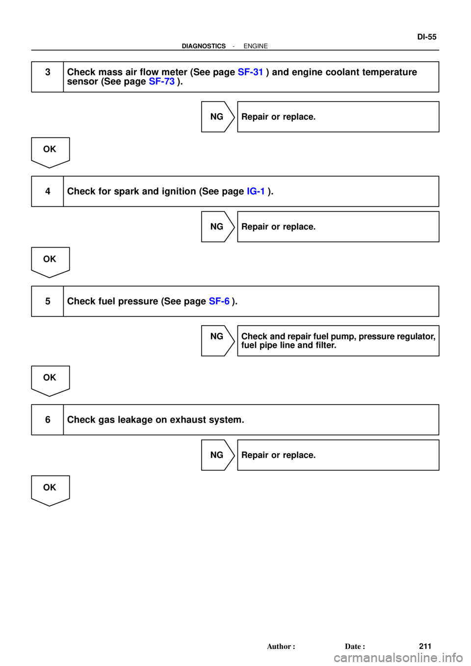
3 Check mass air flow meter (See page SF-31) and engine coolant temperature
sensor (See page SF-73).
NG Repair or replace.
OK
4 Check for spark and ignition (See page IG-1).
NG Repair or replace.
OK
5 Check fuel pressure (See page SF-6).
NG Check and repair fuel pump, pressure regulator,
fuel pipe line and filter.
OK
6 Check gas leakage on exhaust system.
NG Repair or replace.
OK
Page 1043 of 1897
P00495
Outside
Inside
- DIAGNOSTICSENGINE
DI-9
165 Author�: Date�:
2001 AVALON (RM808U)
NO Proceed to page ST-18, and continue to trouble-
shoot.
YES
3 Does engine start?
NO Go to step 7.
YES
4 Check air filter.
PREPARATION:
Remove the air filter.
CHECK:
Visually check that the air filter is not dirty or excessive oily.
HINT:
If necessary, clean the air filter with compressed air. First blow
from inside thoroughly, then blow from outside of the air filter.
NG Repair or replace.
OK
5 Check idle speed.
PREPARATION:
(a) Warm up the engine to normal operating temperature.
(b) Switch off all the accessories.
(c) Switch off the A/C.
(d) Shift the transmission into the N position.
(e) Connect the OBD II scan tool or TOYOTA hand-held tester to the DLC3 on the vehicle.
CHECK:
Use the CURRENT DATA to check the idle speed.
OK:
Idle speed: 650 - 750 rpm
NG Proceed to problem symptoms table on page
DI-22.
1 msec./Division (Idling)
Injection duration
(Magnification) Injector Signal Waveform
DI-62
- DIAGNOSTICSENGINE
218")