Page 276 of 1897

I12518
1. ECU-IG NO. 1 Fuse - 5 A
2. ECU-B NO. 2 Fuse - 7.5 A
3.TAIL Fuse - 10 A
4. SEAT HTR Fuse - 20 A
5. FR P/W Fuse - 20 A
6.GAUGE NO. 1 Fuse - 10 A
7. HTR Fuse - 10 A
8. FOG Fuse - 15 A
9. TURN Fuse - 7.5 A
10. A/C Fuse - 10 A
11. RADIO Fuse - 15 A
12. PANEL Fuse - 5 A
13.FL P/W Fuse - 25 A
14.PWR OUTLET NO. 1 Fuse - 15 A
15. ECU-ACC Fuse - 5 A
16. SRS ACC Fuse - 10 A
17. MIR HTR Fuse - 10 A
18. PWR OUTLET NO. 2 Fuse - 15 A
19. GAUGE NO. 2 Fuse - 10 A
20. OBDII Fuse - 7.5 A
21.STOP Fuse - 15 A
22.DOME Fuse - 7.5 A
23. OPNER Fuse - 5 A
24.RL P/W Fuse - 20 A
25.RR P/W Fuse - 20 A
26. WIP Fuse - 25 A
27.ECU-IG NO. 2 Fuse - 10 A
28.CIG Fuse - 15 A
29.DOOR NO. 1 Fuse - 25 A
30. SUN ROOF Fuse - 30 A
31. DEF Fuse - 40 A
32.PWR SEAT Fuse - 30 A Fuses:
Driver Side Junction Block:
2526
31
32
1234568
21222324
7910
27282930
Relays:
A. FOG Relay
B. DEF Relay
C. IG1 Relay
D. TAIL Relay
E. PWR Relay
F. N/F-1
G.N/F-2
AB
C
D E F G
11121314151718161920
- BODY ELECTRICALPOWER SOURCE
BE-1 1
1615 Author�: Date�:
2001 AVALON (RM808U)
Page 304 of 1897
BE0IP-06
I12542
Instrument Panel Junction Block
� Sun Roof Fuse
� GAUGE No,1 FuseIgnition Switch Sliding Roof Assembly
� Sliding Roof Switch
� Sliding Roof Control ECU
Door Courtesy Switch
BE-102
- BODY ELECTRICALSLIDING ROOF SYSTEM
1706 Author�: Date�:
2001 AVALON (RM808U)
LOCATION
Page 308 of 1897

BE-4
- BODY ELECTRICALTROUBLESHOOTING
1608 Author�: Date�:
2001 AVALON (RM808U)
COMBINATION METER (Meter, Gauges and Illumination):
SymptomSuspect AreaSee page
Tachometer, Fuel Gauge and Engine Coolant Temperature Gauge
do not operate.
1. ECU-B Fuse
2. ECU-IG No. 2 Fuse
3. Meter Circuit Plate
4. Wire Harness
5. Multi Display-
-
BE-43
-
-
Speedometer does not operate.
1. Vehicle Speed Sensor (ABS - ECU)
2. Meter Circuit Plate
3. Wire Harness
4. Multi DisplayBE-53
BE-43
-
-
Tachometer does not operate.
1. EFI - ECU
2. Meter Circuit Plate
3. Wire Harness
4. Multi Display-
BE-43
-
-
Fuel Gauge does not operate or abnormal operation.
1. Fuel Receiver Gauge
2. Fuel Sender Gauge
3. Meter Circuit Plate
4. Wire HarnessBE-53
BE-53
BE-43
-
Engine Coolant Temperature Gauge does not operate or abnormal
operation.
1. Engine Coolant Temperature Receiver Gauge
2. Engine Coolant Temperature Sender Gauge
3. Meter Circuit Plate
4. Wire HarnessBE-53
BE-53
BE-43
-
All illumination lights do not light up.
1. Bulb
2. PANEL Fuse
3. Light Control Rheostat
4. Wire Harness-
-
BE-53
-
Brightness does not change even when rheostat turned.
1. Bulb
2. Rheostat
3. Wire Harness-
-
-
Only one illumination light does not light up.1. Bulb
2. Wire Harness-
-
COMBINATION METER (Warning Lights):
SymptomSuspect AreaSee page
Warning lights do not light up. (Except Discharge, Open Door and
SRS)
1. Bulb
2. GAUGE No. 1 Fuse
3. Meter Circuit Plate
4. Wire Harness-
-
BE-53
-
Low Oil Pressure warning light does not light up.
1. Multi Display
2. Bulb
3. Low Oil Pressure Warning Switch
4. Meter Circuit Plate
5. Wire Harness-
-
BE-53
BE-43
-
Fuel Level warning light does not light up.
1. Multi Display
2. Bulb
3. Fuel Sender Gause
4. Meter Circuit Plate
5. Wire Harness-
-
BE-53
BE-43
-
ABS warning light does not light up.
1. Bulb
2. ABS ECU
3. Wire Harness-
DI-210
-
Page 347 of 1897

BO2OO-01
H12112
Rear Lower FrameDoor Lock Striker23 (230, 17)
Front Door Weatherstrip
Door Glass Run
Outside Rear View
Mirror
Door Glass
Lower Frame
Bracket Garnish
7.8 (80, 69 in.´lbf)25 (260, 19)
5.4 (55, 48 in.´lbf)
Outside Handle
Key Cylinder
5.4 (55, 48 in.´lbf)
Door
Hinge
7.8 (80, 69 in.´lbf)
Door Check
25 (260, 19)
Door Speaker BoardFront Lower
Frame
25 (260, 19)
Door Hinge
Front Door Outside Lower Moulding
Door Lock Protector
Service Hole Cover
5.4 (55, 48 in.´lbf)
� Precoated part
Door LockInside Handle
4.9 (50, 43 in.´lbf)
Inside Handle
Bezel
Cover
Door TrimUpper Armrest
Base Panel
Power Window Switch
Front Door Armrest
Courtesy Light
Front Door
Belt Moulding Front Door
Inner Weatherstrip
x10
5.4 (55, 48 in.´lbf)
Window Regulator
Guide Assembly
5.4 (55, 48 in.´lbf)
x8
x4
Window Regulator Motor
No. 2 Service Hole Cover
Front Door Trim Pocket : Specified torqueN´m (kgf´cm, ft´lbf)
BO-8
- BODYFRONT DOOR
1793 Author�: Date�:
2001 AVALON (RM808U)
FRONT DOOR
COMPONENTS
Page 348 of 1897

BO2OP-01
H04751
H12102
H12103
H12137
x10
x8
- BODYFRONT DOOR
BO-9
1794 Author�: Date�:
2001 AVALON (RM808U)
DISASSEMBLY
1. REMOVE INSIDE HANDLE BEZEL
(a) Using a screwdriver, remove the cover.
HINT:
Tape the screwdriver tip before use.
(b) Remove the screw.
(c) Using a screwdriver, remove the inside handle bezel as
shown in the illustration.
HINT:
Tape the screwdriver tip before use.
2. REMOVE COURTESY LIGHT
3. REMOVE UPPER ARMREST BASE PANEL WITH
POWER WINDOW SWITCH
(a) Using a screwdriver, remove the upper armrest base pan-
el with power window switch.
HINT:
Tape the screwdriver tip before use.
(b) Disconnect the connector.
(c) Remove the 3 screws and power window switch from the
upper armrest base panel.
4. REMOVE DOOR TRIM
(a) Using a screwdriver, remove the 2 caps.
HINT:
Tape the screwdriver tip before use.
(b) Remove the 6 screws and clip.
(c) Pull the trim upward to remove it.
(d) Using a screwdriver, remove the front door inner weather-
strip from the front door trim.
(e) Remove the 10 screws and front door armrest from the
front door trim.
(f) Remove the 8 screws and front door trim pocket from the
front door trim.
Page 350 of 1897

H12107
Protective Tape
H12108
H02440
- BODYFRONT DOOR
BO-1 1
1796 Author�: Date�:
2001 AVALON (RM808U)
11. REMOVE FRONT DOOR BELT MOULDING
(a) Apply protective tape to the outer surface as shown in the
illustration, to keep the surface from being scratched.
(b) Using a moulding remover, remove the front door belt
moulding.
12. REMOVE FRONT DOOR OUTSIDE LOWER MOULD-
ING
(a) Using a drill of less than ù3.2 mm (0.126 in.), drill out the
3 rivet heads.
HINT:
Gently and vertically put the drill to the rivets, and cut the rivet
flanges.
CAUTION:
Take care as the cut rivets are hot.
NOTICE:
Prizing the hole with a drill can lead to damage to the rivet
hole or the drill itself.
(b) Using a clip remover, remove the clip.
(c) Remove the front door outside lower moulding.
(d) Using a vacuum cleaner, remove the drilled rivets and
accociated metallic dust from the inside of door panel.
HINT:
At the time of reassembly, please refer to the following item.
Using an air riveter with nose piece No. 1 or a hand riveter with
nose piece No. 1 to install new 3 rivets to the front door outside
lower moulding.
NOTICE:
�At the time of reassembly, please refer to the follow-
ing items.
�Do not prize a riveter, as riveter is damaged, it is not
tightened and the mandrel is bent.
Page 377 of 1897

BO2PU-02
H12194: Specified torqueN´m (kgf´cm, ft´lbf)
AA
KK
K
K
K
K
K
K
B
L
E
G
GG
G
GG
G
GGI
C
C
C
C
K
K
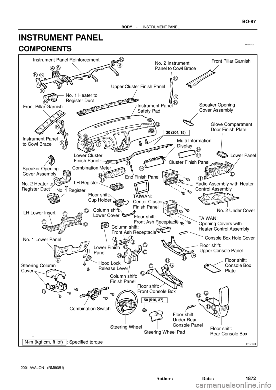
KKB Instrument Panel Reinforcement
No. 2 Instrument
Panel to Cowl BraceFront Pillar Garnish
Upper Cluster Finish Panel
Instrument Panel
Safety Pad Front Pillar GarnishNo. 1 Heater to
Register Duct
Instrument Panel
to Cowl BraceSpeaker Opening
Cover Assembly
H
H
H
H
H
H
III
G
D EDD
Steering Wheel
Floor shift:
Rear Console Box Floor shift:
Front Console Box
Combination Switch No. 1 Lower PanelLH Lower Insert
Column shift:
Finish Panel Hood Lock
Release LeverNo. 2 Under Cover
Floor shift:
Console Box
Plate
Steering Wheel Pad Steering Column
Cover
Floor shift:
Front Ash Receptacle
Floor shift:
Upper Console PanelLower Finish
Panel Column shift:
Lower Cover LH Register
TAIWAN:
Center Cluster
Finish Panel
TAIWAN:
Opening Covers with
Heater Control Assembly Radio Assembly with Heater
Control AssemblyLower Panel
Cluster Finish Panel
End Finish Panel Combination Meter Lower Cluster
Finish PanelGlove Compartment
Door Finish Plate
Speaker Opening
Cover Assembly
No. 2 Heater to
Register Duct
No. 1 Register
Floor shift:
Cup Holder
Multi Information
Display
Floor shift:
Under Rear
Console Panel
I
HH
50 (510, 37)
20 (204, 15)
N
JJJJConsole Box Hole Cover
Column shift:
Front Ash Receptacle
- BODYINSTRUMENT PANEL
BO-87
1872 Author�: Date�:
2001 AVALON (RM808U)
INSTRUMENT PANEL
COMPONENTS
Page 383 of 1897

BO2PV-01
H12176
2 Clips
H121774 Clips
H12178
4 Clips
H12181
BO-90
- BODYINSTRUMENT PANEL
1875 Author�: Date�:
2001 AVALON (RM808U)
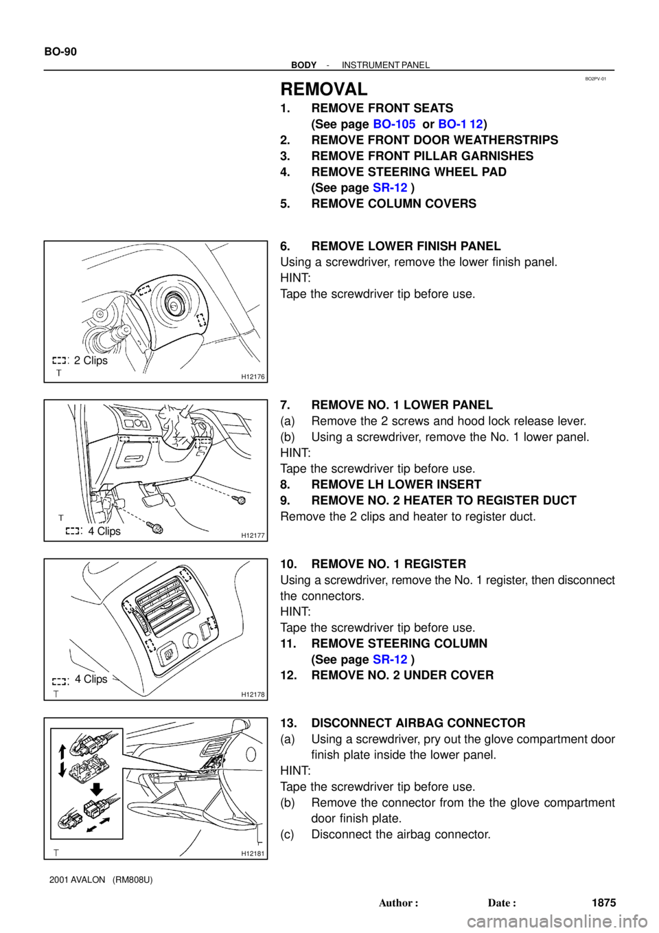
REMOVAL
1. REMOVE FRONT SEATS
(See page BO-105 or BO-1 12)
2. REMOVE FRONT DOOR WEATHERSTRIPS
3. REMOVE FRONT PILLAR GARNISHES
4. REMOVE STEERING WHEEL PAD
(See page SR-12)
5. REMOVE COLUMN COVERS
6. REMOVE LOWER FINISH PANEL
Using a screwdriver, remove the lower finish panel.
HINT:
Tape the screwdriver tip before use.
7. REMOVE NO. 1 LOWER PANEL
(a) Remove the 2 screws and hood lock release lever.
(b) Using a screwdriver, remove the No. 1 lower panel.
HINT:
Tape the screwdriver tip before use.
8. REMOVE LH LOWER INSERT
9. REMOVE NO. 2 HEATER TO REGISTER DUCT
Remove the 2 clips and heater to register duct.
10. REMOVE NO. 1 REGISTER
Using a screwdriver, remove the No. 1 register, then disconnect
the connectors.
HINT:
Tape the screwdriver tip before use.
11. REMOVE STEERING COLUMN
(See page SR-12)
12. REMOVE NO. 2 UNDER COVER
13. DISCONNECT AIRBAG CONNECTOR
(a) Using a screwdriver, pry out the glove compartment door
finish plate inside the lower panel.
HINT:
Tape the screwdriver tip before use.
(b) Remove the connector from the the glove compartment
door finish plate.
(c) Disconnect the airbag connector.