Page 8 of 1897

AC20C-02
N13793
Charging Cylinder High Pressure
Service Valve Low Pressure
Service ValvePush
Air
N13792
Gas Leak
Detector AC-12
- AIR CONDITIONINGAIR CONDITIONING SYSTEM
1934 Author�: Date�:
2001 AVALON (RM808U)
CHARGING
1. INSTALL CHARGING CYLINDER
HINT:
When handling the charging cylinder, always follow the direc-
tions given in the instruction manual.
(a) Charge the proper amount of refrigerant into the charging
cylinder.
(b) Connect the center hose to the charging cylinder.
CAUTION:
Do not open both high and low hand valves of manifold
gauge set.
(c) Open the valve of charging cylinder.
(d) Press the valve core on the side of manifold gauge and
expel the air inside of the center hose.
2. INSPECT REFRIGERATION SYSTEM FOR LEAKS
(a) Open the high pressure hand valve and charge refriger-
ant.
(b) When the low pressure gauge indicates 98 kPa
(1 kgf/cm
2, 14 psi) close the high pressure hand valve.
(c) Using a gas leak detector, check the system for leakage.
If leak is found, repair the faulty component or connection.
CAUTION:
Use the refrigerant recovery/ recycling machine to recover
the refrigerant whenever replacing parts.
Page 590 of 1897

INSTALLATION
1. PLACE THERMOSTAT IN WATER PUMP
(a) Install a new gasket on to the th")
CO02T-03
B04153Stud BoltJiggle Valve
15°15°
CO-12
- COOLINGTHERMOSTAT
1205 Author�: Date�:
2001 AVALON (RM808U)
INSTALLATION
1. PLACE THERMOSTAT IN WATER PUMP
(a) Install a new gasket on to the thermostat.
(b) Align the thermostat jiggle valve with the upper stud bolt,
and insert the thermostat in the water inlet housing.
HINT:
The jiggle valve may be set within 15° of either side of the pre-
scribed position.
2. INSTALL WATER INLET
Install the water inlet with the 3 nuts.
Torque: 8 N´m (80 kgf´cm, 69 in.´lbf)
3. INSTALL WATER INLET PIPE
(a) Install a new O-ring to the water inlet pipe.
(b) Apply soapy water to the O-ring.
(c) Connect the water inlet pipe to the water inlet.
(d) Install the bolt holding the water inlet pipe to the LH cylin-
der head.
Torque: 19.5 N´m (200 kgf´cm, 14 ft´lbf)
4. INSTALL ENGINE WIRE PROTECTOR
5. CONNECT NO.2 ECT SWITCH CONNECTOR
6. CONNECT HEATER HOSES
7. REINSTALL AIR CLEANER HOSE WITH RESONATOR
8. INSTALL V-BANK COVER
(a) Using 5 mm hexagon wrench, install the V-bank cover
with the 3 cap nuts.
(b) Press down the V-bank cover fastener.
9. FILL WITH ENGINE COOLANT
10. START ENGINE AND CHECK FOR LEAKS
11. RECHECK ENGINE COOLANT LEVEL
Page 927 of 1897

Platinum
Electrode
Heater
A/F Sensor Voltage
Air-Fuel Ratio
(V)
2.6 4.0
3.8
3.6
3.4
3.2
3.0
2.8
2.4
12 13 14")
A00477
Atmosphere
Cover
Exhaust GasPlatinum
Electrode
Solid Electrolyte
(Zirconia Element)
Platinum
Electrode
Heater
A/F Sensor Voltage
Air-Fuel Ratio
(V)
2.6 4.0
3.8
3.6
3.4
3.2
3.0
2.8
2.4
12 13 14 15 16 17 18
Coating (Ceramic)
ECM Monitored
19
Housing
- DIAGNOSTICSENGINE
DI-43
199 Author�: Date�:
2001 AVALON (RM808U)
DTC P0125 Insufficient Coolant Temp. for Closed Loop
Fuel Control
CIRCUIT DESCRIPTION
To obtain a high purification rate for the CO, HC and NOx components of the exhaust gas, a three-way cata-
lytic converter is used, but for the most efficient use of the three-way catalytic converter, the air-fuel ratio
must be precisely controlled so that it is always close to the stoichiometric air-fuel ratio.
The A/F sensor has the characteristic that provides output voltage* approximately proportional to the exist-
ing air-fuel ratio. The A/F sensor output voltage* is used to provide feedback for the ECM to control the air-
fuel ratio.
By the A/F sensor output, the ECM can determine the deviation amount from the stoichiometric air-fuel ratio
and control the proper injection time immediately. If the A/F sensor is malfunctioning, ECM is unable to per-
form accurate air-fuel ratio control.
The A/F sensor is equipped with a heater which heats the zirconia element. The heater is controlled by the
ECM. When the intake air volume is low (the temp. of the exhaust gas is low), current flows to the heater
to heat the sensor for accurate oxygen concentration detection.
*: The voltage value changes at the inside of the ECM only.
DTC No.DTC Detecting ConditionTrouble Area
P0125
After engine is warmed up, A/F sensor output* does not
change when conditions (a), (b), (c) and (d) continue for at
least 1.5 min:
*: Output value changes at inside of the ECM only
(a) Engine speed: 1,500 rpm or more
(b) Vehicle speed: 40 - 100 km/h (25 - 62 mph)
(c) Throttle valve is not fully closed
(d) 140 sec. or more after starting engine�Open or short in A/F sensor (bank 1, 2 sensor 1) circuit
�A/F sensor (bank 1, 2 sensor 1)
�Air inducation system
�Fuel pressure
�Injector
�Gas leakage on exhaust sytem
�ECM
HINT:
�After confirming DTC P0125, use the OBD II scan tool or TOYOTA hand-held tester to confirm voltage
output of the A/F sensor (bank 1, 2 sensor 1) from the CURRENT DATA.
�The ECM controls the voltage of the AFR+, AFL+, AFR- and AFL- terminals of the ECM to the fixed
voltage. Therefore, it is impossible to confirm the A/F sensor output voltage without the OBDII scan
tool or TOYOTA hand-held tester.
DI07M-14
Page 1008 of 1897
- DIAGNOSTICSENGINE
DI-129
285 Author�: Date�:
2001 AVALON (RM808U)
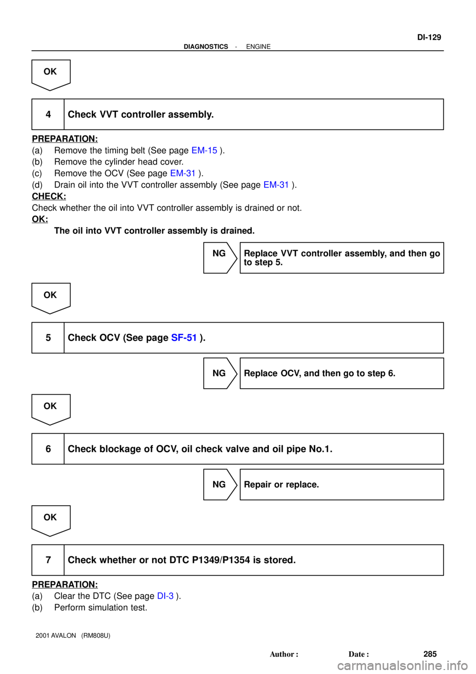
OK
4 Check VVT controller assembly.
PREPARATION:
(a) Remove the timing belt (See page EM-15).
(b) Remove the cylinder head cover.
(c) Remove the OCV (See page EM-31).
(d) Drain oil into the VVT controller assembly (See page EM-31).
CHECK:
Check whether the oil into VVT controller assembly is drained or not.
OK:
The oil into VVT controller assembly is drained.
NG Replace VVT controller assembly, and then go
to step 5.
OK
5 Check OCV (See page SF-51).
NG Replace OCV, and then go to step 6.
OK
6 Check blockage of OCV, oil check valve and oil pipe No.1.
NG Repair or replace.
OK
7 Check whether or not DTC P1349/P1354 is stored.
PREPARATION:
(a) Clear the DTC (See page DI-3).
(b) Perform simulation test.
Page 1011 of 1897
DI-132
- DIAGNOSTICSENGINE
288 Author�: Date�:
2001 AVALON (RM808U)
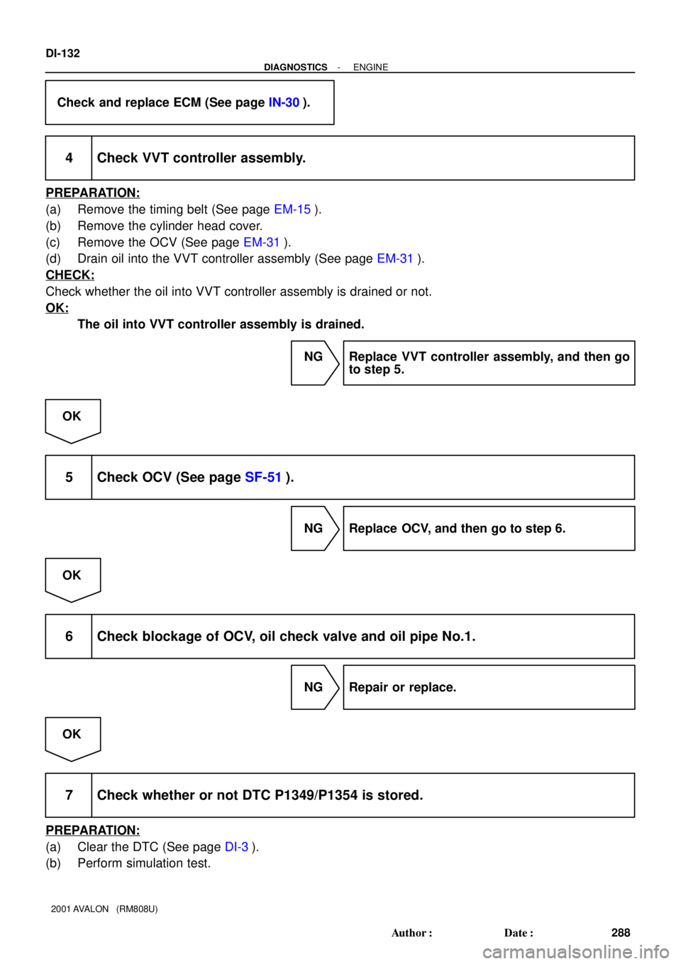
Check and replace ECM (See page IN-30).
4 Check VVT controller assembly.
PREPARATION:
(a) Remove the timing belt (See page EM-15).
(b) Remove the cylinder head cover.
(c) Remove the OCV (See page EM-31).
(d) Drain oil into the VVT controller assembly (See page EM-31).
CHECK:
Check whether the oil into VVT controller assembly is drained or not.
OK:
The oil into VVT controller assembly is drained.
NG Replace VVT controller assembly, and then go
to step 5.
OK
5 Check OCV (See page SF-51).
NG Replace OCV, and then go to step 6.
OK
6 Check blockage of OCV, oil check valve and oil pipe No.1.
NG Repair or replace.
OK
7 Check whether or not DTC P1349/P1354 is stored.
PREPARATION:
(a) Clear the DTC (See page DI-3).
(b) Perform simulation test.
Page 1321 of 1897
A06660
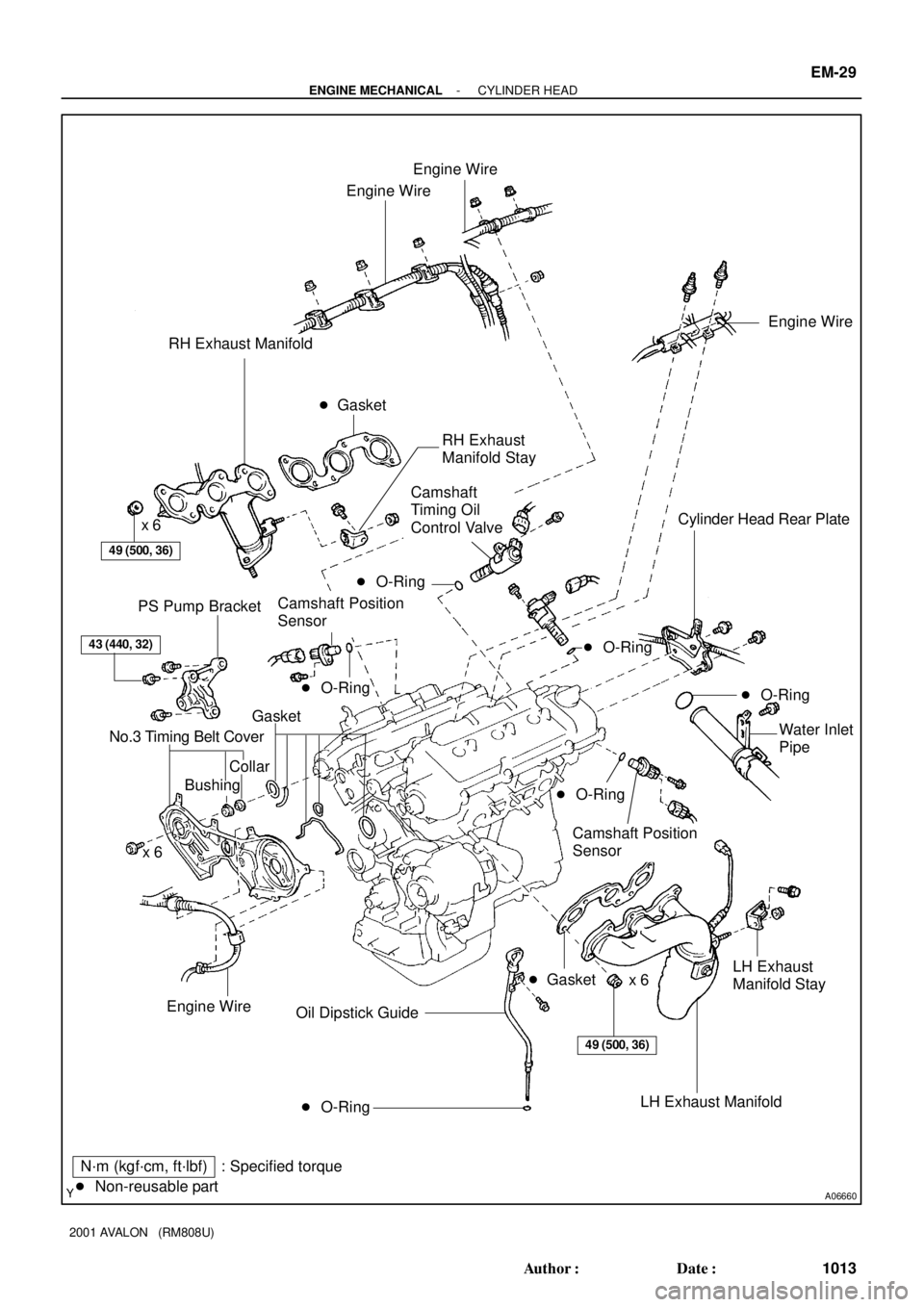
Engine Wire
Engine Wire
RH Exhaust Manifold
49 (500, 36)
x 6Cylinder Head Rear Plate
PS Pump Bracket
43 (440, 32)
Gasket
No.3 Timing Belt Cover
CollarWater Inlet
Pipe
x 6
� O-Ring Oil Dipstick Guide
N´m (kgf´cm, ft´lbf) : Specified torque
� Non-reusable part� Gasket
Engine Wire
Engine Wire
49 (500, 36)
Bushing
Camshaft Position
Sensor
LH Exhaust
Manifold Stay
x 6
� Gasket
� O-Ring
� O-Ring
LH Exhaust Manifold
� O-Ring
Camshaft
Timing Oil
Control Valve
Camshaft Position
SensorRH Exhaust
Manifold Stay
� O-Ring
� O-Ring
- ENGINE MECHANICALCYLINDER HEAD
EM-29
1013 Author�: Date�:
2001 AVALON (RM808U)
Page 1322 of 1897

A05703
Adjusting Shim
Valve Lifter
Keeper
Spring Retainer
Valve Spring
Spring Seat
� Oil Seal
Valve � Valve Guide BushingLH Cylinder Head Cover
LH Intake
Camshaft
Snap Ring Camshaft Sub-Gear
LH Exhaust
Camshaft RH Cylinder Head Cover
Gasket
RH Intake
Camshaft Camshaft Sub-Gear
Camshaft Gear Spring
RH Exhaust
CamshaftWave Washer
Semi-Circular PlugSemi-Circular
Plug
LH Cylinder Head
Camshaft
Bearing Cap
� Camshaft Oil Seal RH Cylinder Head
� RH Cylinder
Head Gasket
� LH Cylinder Head Gasket18 (185, 13)x 8
16 (160, 12)
See Page EM-59
1st 54 (550, 40)
2nd Turn 90°
N´m (kgf´cm, ft´lbf) : Specified torque
� Non-reusable part
� Spark Plug
Tube Gasket
Wave WasherGasketSnap RingCamshaft Gear Spring
Oil Control Valve Filter
� Gasket
Camshaft Timing
Gear (VVT-i)
� Gasket
� Gasket
Oil Control
Valve FilterCylinder Head
Rear CoverCylinder Head
Rear Cover� Gasket
150 (1,530, 110)
NOTICE:
Intake Camshaft
Do not remove or install the camshaft timing
gear (VVT-i) beside changing VVT-i or the
camshaft.
�
EM-30
- ENGINE MECHANICALCYLINDER HEAD
1014 Author�: Date�:
2001 AVALON (RM808U)
Page 1323 of 1897
EM0ZF-02
P12683
A05224
SST
P12686
P12720
Magnetic Finger
A05276
EM-40
- ENGINE MECHANICALCYLINDER HEAD
1024 Author�: Date�:
2001 AVALON (RM808U)
DISASSEMBLY
1. REMOVE VALVE LIFTERS AND SHIMS
HINT:
Arrange the valve lifters and shims in the correct order.
2. REMOVE VALVES
(a) Using SST, compress the valve spring and remove the 2
keepers.
SST 09202-70020 (09202-00010)
(b) Remove the spring retainer, valve spring and valve.
(c) Using needle-nose pliers, remove the oil seal.
(d) Using compressed air and a magnetic finger, remove the
spring seat by blowing air.
HINT:
Arrange the valves, valve springs, spring seats and spring re-
tainers in the correct order.
3. REMOVE CYLINDER HEAD REAR COVER
Remove the 6 bolts, rear cover and gasket.