Page 1342 of 1897

11. INSTALL RH EXHAUST MANIFOL")
A06661
Manifold
Stay
A07283
New O-Ring
A07281
Manifold
Stay
A05188Inlet PipeRear
Plate
EM-66
- ENGINE MECHANICALCYLINDER HEAD
1050 Author�: Date�:
2001 AVALON (RM808U)
11. INSTALL RH EXHAUST MANIFOLD
(a) Install a new gasket and the exhaust manifold with the 6
nuts. Uniformly tighten the nuts in several passes.
Torque: 49 N´m (500 kgf´cm, 36 ft´lbf)
(b) Install the exhaust manifold stay with the bolt and nut. Al-
ternately tighten the bolt and nut.
Torque: 34 N´m (350 kgf´cm, 25 ft´lbf)
(c) Connect the A/F sensor connector.
12. INSTALL OIL DIPSTICK AND GUIDE
(a) Install a new O-ring to the dipstick guide.
(b) Apply soapy water to the O-ring.
(c) Push in the dipstick guide end into the guide hole of the
No.1 oil pan.
(d) Install the dipstick guide with the bolt.
Torque: 8 N´m (80 kgf´cm, 69 in.´lbf)
(e) Install the dipstick.
13. INSTALL LH EXHAUST MANIFOLD
(a) Install a new gasket and the exhaust manifold with the 6
nuts. Uniformly tighten the nuts in several passes.
Torque: 49 N´m (500 kgf´cm, 36 ft´lbf)
(b) Install the exhaust manifold stay with the bolt and nut. Al-
ternately tighten the bolt and nut.
Torque: 34 N´m (350 kgf´cm, 25 ft´lbf)
(c) Connect the A/F sensor connector.
14. INSTALL WATER INLET PIPE
(a) Install a new O-ring to the water inlet pipe.
(b) Apply soapy water to the O-ring.
(c) Connect the water inlet pipe to the water inlet.
(d) Install the bolt holding the water inlet pipe to the cylinder
head.
Torque: 19.5 N´m (200 kgf´cm, 14 ft´lbf)
15. INSTALL CYLINDER HEAD REAR PLATE
Torque: 8 N´m (80 kgf´cm, 69 in.´lbf)
16. INSTALL ENGINE WIRE PROTECTOR
17. INSTALL CAMSHAFT TIMING OIL CONTROL VALVES
18. INSTALL CAMSHAFT POSITION SENSORS
19. INSTALL NO.3 TIMING BELT COVER
(a) Check that the timing belt cover gaskets have no cracks
or peeling, etc.
If the gaskets have cracks or peeling etc., replace them using
these steps:
�Using a screwdriver and gasket scraper, remove all
the old gasket material.
Page 1345 of 1897

(n) Install the PS pressure tube with the 2 nuts.
(o) Connect the throttle position sensor connector.
(p) Connect the")
- ENGINE MECHANICALCYLINDER HEAD
EM-69
1053 Author�: Date�:
2001 AVALON (RM808U)
(n) Install the PS pressure tube with the 2 nuts.
(o) Connect the throttle position sensor connector.
(p) Connect the IAC valve connector.
(q) Connect the No.1 VSV connector for the ACIS.
(r) Connect the No.2 VSV connector for the ACIS.
(s) Connect the VSV connecter for the EVAP.
(t) Connect the DLC1 to the bracket on the intake air control
valve.
(u) Connect the throttle cable.
(v) Connect the accelerator cable.
29. INSTALL AIR CLEANER CAP HOSE WITH RESONA-
TOR
30. INSTALL V-BANK COVER
(a) Using a 5 mm hexagon wrench, install the V-bank cover
with the 3 cap nuts.
(b) Press down the V-bank cover fastener.
31. INSTALL FRONT EXHAUST PIPE (See page EM-77)
32. INSTALL PS PUMP (See page SR-35)
33. INSTALL GENERATOR DRIVE BELT
(See page CH-16)
34. FILL WITH ENGINE COOLANT
35. START ENGINE AND CHECK FOR LEAKS
36. VEHICLE ROAD TEST
Check for abnormal noise, shock, slippage, correct shift points
and smoothly operation.
37. RECHECK ENGINE COOLANT LEVEL
Page 1347 of 1897
A05276
P12719
SST
Z19062
Intake ExhaustMark
ºNOKº or
ºFN , INº
Light Brown SurfaceGray Surface
P12668
(4)
(3)
(2)
(1)
A05224
SST
- ENGINE MECHANICALCYLINDER HEAD
EM-57
1041 Author�: Date�:
2001 AVALON (RM808U)
4. INSTALL CYLINDER HEAD REAR COVER
Install the rear cover and gasket with the 6 bolts.
Torque: 10 N´m (100 kgf´cm, 7.3 ft´lbf)
5. INSTALL VALVES
(a) Using SST, push in a new oil seal.
SST 09201-41020
HINT:
The intake valve oil seal is light brown and the exhaust valve oil
seal is gray.
NOTICE:
Pay much attention when assembling the oil seal for intake
and exhaust. Assembling the wrong one may cause a fail-
ure.
(b) Install the valve (1), spring seat (2), valve spring (3) and
spring retainer (4).
(c) Using SST, compress the valve spring and place the 2
keepers around the valve stem.
SST 09202-70020 (09202-00010)
Page 1349 of 1897

(k) (l)
- ENGINE MECHANICALCYLINDER HEAD
EM-31
1015 Author�: Date�:
2001 AVALON (RM808U)
REMOVAL
NOTICE:
Do not remove or install the camshaft timing g")
EM0ZE-02
A10518
5 mm
Hexagon
Wrench
A06658
(j)
(k) (l)
- ENGINE MECHANICALCYLINDER HEAD
EM-31
1015 Author�: Date�:
2001 AVALON (RM808U)
REMOVAL
NOTICE:
Do not remove or install the camshaft timing gear (VVT-i)
beside changing VVT-i or the camshaft.
1. DRAIN ENGINE COOLANT
2. REMOVE RH FENDER APRON SEAL
3. REMOVE GENERATOR DRIVE BELT
(See page CH-6)
4. REMOVE PS PUMP (See page SR-27)
5. REMOVE FRONT EXHAUST PIPE (See page EM-72)
6. REMOVE V-BANK COVER
(a) Using a 5 mm hexagon wrench, remove the 3 cap nuts.
(b) Loosen the V-bank cover fastener counterclockwise.
(c) Remove the V-bank cover.
7. REMOVE AIR CLEANER HOSE WITH RESONATOR
8. REMOVE AIR INTAKE CHAMBER ASSEMBLY
(a) Disconnect the accelerator cable.
(b) Disconnect the throttle cable.
(c) Disconnect the throttle position sensor connector.
(d) Disconnect the IAC valve connector.
(e) Disconnect the No.1 VSV connector for the ACIS.
(f) Disconnect the No.2 VSV connector for the ACIS.
(g) Disconnect the VSV connector for the EVAP.
(h) Disconnect the DLC1 from the bracket on the intake air
control valve.
(i) Remove the 2 nuts, and disconnect the PS pressure tube
from the No.1 engine hanger.
(j) Disconnect the PCV hose from the PCV valve on the RH
cylinder head.
(k) Disconnect the ground strap and cable from the intake air
control valve for the ACIS.
(l) Disconnect the ground cable from the air intake chamber.
Page 1351 of 1897

(d) Remove the 9 bolts, 2 nuts, 2 plate washers, the intake
manif")
A07428
P20049Gasket
A05077
Clamp
Clamp
Clamp
A10531
- ENGINE MECHANICALCYLINDER HEAD
EM-33
1017 Author�: Date�:
2001 AVALON (RM808U)
(d) Remove the 9 bolts, 2 nuts, 2 plate washers, the intake
manifold, delivery pipes and injectors assembly.
NOTICE:
�Be careful not to drop the injectors when removing
the delivery pipes.
�Pay attention to put any hung load on the injector to
and from the side direction.
10. REMOVE WATER OUTLET
(a) Disconnect the ECT sender gauge connector.
(b) Disconnect the ECT sensor connector.
(c) Disconnect the ground strap connector.
(d) Disconnect the upper radiator hose.
(e) Disconnect the engine coolant reservoir hose.
(f) Remove the 2 bolts, 2 nuts and 2 plate washers.
(g) Disconnect the water bypass hose, and remove the water
outlet.
(h) Remove the 2 gaskets.
11. REMOVE IGNITION COILS
12. REMOVE SPARK PLUGS
13. REMOVE TIMING BELT (See page EM-15)
14. REMOVE CAMSHAFT TIMING PULLEYS
(See page EM-15)
15. REMOVE NO.2 IDLER PULLEY (See page EM-15)
16. REMOVE NO.3 TIMING BELT COVER
(a) Disconnect the 3 engine wire clamps from the timing belt
cover.
(b) Remove the 6 bolts and timing belt cover.
17. REMOVE CAMSHAFT POSITION SENSORS
18. REMOVE CAMSHAFT TIMING OIL CONTROL VALVES
19. DISCONNECT ENGINE WIRE PROTECTOR FROM
REAR SIDE
Remove the nut, and disconnect the engine wire protector from
the RH cylinder head.
Page 1384 of 1897

P18815
EM-24
- ENGINE MECHANICALTIMING BELT
1008 Author�: Date�:
2001 AVALON (RM808U)
10. CHECK VALVE TIMING
(a) Slowly turn the crankshaft 2 revol")
P18808
A05052
P12983
Length = 1,410 mm (55.51 in.)
P18815
EM-24
- ENGINE MECHANICALTIMING BELT
1008 Author�: Date�:
2001 AVALON (RM808U)
10. CHECK VALVE TIMING
(a) Slowly turn the crankshaft 2 revolutions, and align the tim-
ing marks of the crankshaft timing pulley and oil pump
body.
NOTICE:
Always turn the crankshaft clockwise.
(b) Check that the timing marks of the RH and LH timing pul-
leys with the timing marks of the No.3 timing belt cover as
shown in the illustration.
If the marks do not align, remove the timing belt and reinstall it.
(c) Remove the crankshaft pulley bolt.
11. INSTALL RH ENGINE MOUNTING BRACKET
Torque: 28 N´m (290 kgf´cm, 21 ft´lbf)
12. INSTALL NO.2 TIMING BELT COVER
(a) Check that the timing belt cover gasket has no cracks or
peeling, etc.
If the gasket has cracks or peeling, etc., replace it using these
steps:
�Using a screwdriver and gasket scraper, remove all
the old gasket material.
�Thoroughly clean all components to remove all the
loose material.
�Remove the backing paper from a new gasket and
install the gasket evenly to the part of the timing belt
cover shaded black in the illustration.
�After installing the gasket, press down on it so that
the adhesive firmly sticks to the timing belt cover.
(b) Install the timing belt cover with the 5 bolts.
Torque: 8.5 N´m (85 kgf´cm, 74 in.´lbf)
(c) Install the engine wire protector clamps to the No.3 timing
belt cover.
13. INSTALL TIMING BELT GUIDE
Install the timing belt guide, facing the cup side outward.
Page 1390 of 1897

VALVE CLEARANCE
INSPECTION
HINT:
Inspect and adjust")
EM03V-03
P18805
A05273
RH EX
RH IN
LH IN
LH EX 3 3
11Front
2266 EM-4
- ENGINE MECHANICALVALVE CLEARANCE
988 Author�: Date�:
2001 AVALON (RM808U)
VALVE CLEARANCE
INSPECTION
HINT:
Inspect and adjust the valve clearance when the engine is cold.
1. REMOVE RH FENDER APRON SEAL
2. DRAIN ENGINE COOLANT
3. REMOVE V-BANK COVER
(a) Using a 5 mm hexagon wrench, remove the 3 cap nuts.
(b) Loosen the V-bank cover fastener counterclockwise.
(c) Remove the V-bank cover.
4. REMOVE AIR INTAKE CHAMBER ASSEMBLY (See
page EM-31)
5. REMOVE IGNITION COILS
6. DISCONNECT UPPER RADIATOR HOSE FROM WA-
TER OUTLET
7. REMOVE CYLINDER HEAD COVERS
(See page EM-31)
8. SET NO.1 CYLINDER TO TDC/COMPRESSION
(a) Turn the crankshaft pulley, and align its groove with the
timing mark º0º of the No.1 timing belt cover.
(b) Check that the valve lifters on the No.1 (IN and EX) are
loose.
If not, turn the crankshaft 1 revolution (360°) and align the mark
as above.
9. INSPECT VALVE CLEARANCE
(a) Check only those valves indicated in the illustration.
(1) Using a feeler gauge, measure the clearance be-
tween the valve lifter and camshaft.
(2) Record out of specification valve clearance mea-
surements. They will be used later to determine the
required replacement adjusting shim.
Valve clearance (Cold):
Intake0.15 - 0.25 mm (0.006 - 0.010 in.)
Exhaust0.25 - 0.35 mm (0.010 - 0.014 in.)
Page 1393 of 1897
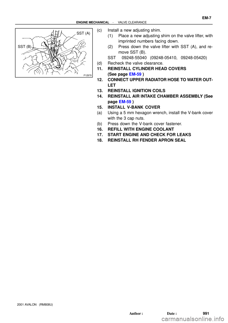
P12979
SST (A)
SST (B)
- ENGINE MECHANICALVALVE CLEARANCE
EM-7
991 Author�: Date�:
2001 AVALON (RM808U)
(c) Install a new adjusting shim.
(1) Place a new adjusting shim on the valve lifter, with
imprinted numbers facing down.
(2) Press down the valve lifter with SST (A), and re-
move SST (B).
SST 09248-55040 (09248-05410, 09248-05420)
(d) Recheck the valve clearance.
11. REINSTALL CYLINDER HEAD COVERS
(See page EM-59)
12. CONNECT UPPER RADIATOR HOSE TO WATER OUT-
LET
13. REINSTALL IGNITION COILS
14. REINSTALL AIR INTAKE CHAMBER ASSEMBLY (See
page EM-59)
15. INSTALL V-BANK COVER
(a) Using a 5 mm hexagon wrench, install the V-bank cover
with the 3 cap nuts.
(b) Press down the V-bank cover fastener.
16. REFILL WITH ENGINE COOLANT
17. START ENGINE AND CHECK FOR LEAKS
18. REINSTALL RH FENDER APRON SEAL