Page 898 of 1897
A11425
EFI No.1
FL
MainIG Switch
AM2
BatteryEFI Relay
C/OPN Relay
Fuel Pump
ST
RelayStarter Park/ Neutral
Position SwitchECM
FC
Tr
STA
NE (STA Signal)
(NE Signal) MAINMREL
IGSW
ST DI-152
- DIAGNOSTICSENGINE
308 Author�: Date�:
2001 AVALON (RM808U)
Fuel Pump Control Circuit
CIRCUIT DESCRIPTION
In the diagram below, when the engine is cranked, current flows from terminal ST of the ignition switch to
the starter relay (Marking: ST) coil and also current flows to terminal STA of ECM (STA signal).
When the STA signal and NE signal are input to the ECM, Tr is turned ON, current flows to coil of the circuit
opening relay (Marking: C/OPN), the relay switches on, power is supplied to the fuel pump and the fuel pump
operates.
While the NE signal is generated (engine running), the ECM keeps Tr ON (circuit opening relay ON) and the
fuel pump also keeps operating.
DI6TE-01
Page 899 of 1897
A11672
From
Terminal
MREL of
ECM From
Battery1 5
2 B-R3
C/OPN Relay Driver Side R/B No.6
6
66 6 B-R 1
IF1 W-R
W-B
2C
2F13
EFI
No.1 AM2
EFI Relay 5
1B
EDEngine Room J/B
43
22B
1 2G
46 7
2C 2
BK 7 4
IF1ECM
E01
ID2E8
Fuel
Pump
AL-B
W-BJ11
J/CFC
G-B3
5 41
L-B B-O IG SwitchW-B
W-R
L-O
BE6653A02330
A02405
ON
- DIAGNOSTICSENGINE
DI-153
309 Author�: Date�:
2001 AVALON (RM808U)
WIRING DIAGRAM
INSPECTION PROCEDURE
TOYOTA hand-held tester:
1 Connect TOYOTA hand-held tester, and check operation of fuel pump.
PREPARATION:1
(a) Connect the TOYOTA hand-held tester to the DLC3.
(b) Turn the ignition switch ON and push the TOYOTA hand-
held tester main switch ON.
(c) Use the ACTIVE TEST mode to operate the fuel pump.
CHECK:
Check that the pulsation damper screw rises up when the fuel
pump is operated by the TOYOTA hand-held tester.
OK:
The pulsation damper screw rises up.
OK Check for starter signal circuit
(See page DI-142).
NG
Page 900 of 1897
A02064
ON
FC
(+) (-)
DI-154
- DIAGNOSTICSENGINE
310 Author�: Date�:
2001 AVALON (RM808U)
2 Check for ECM power source circuit (See page DI-148).
NG Repair or replace.
OK
3 Check circuit opening relay (Marking: C/OPN) (See page SF-63).
NG Replace circuit opening relay.
OK
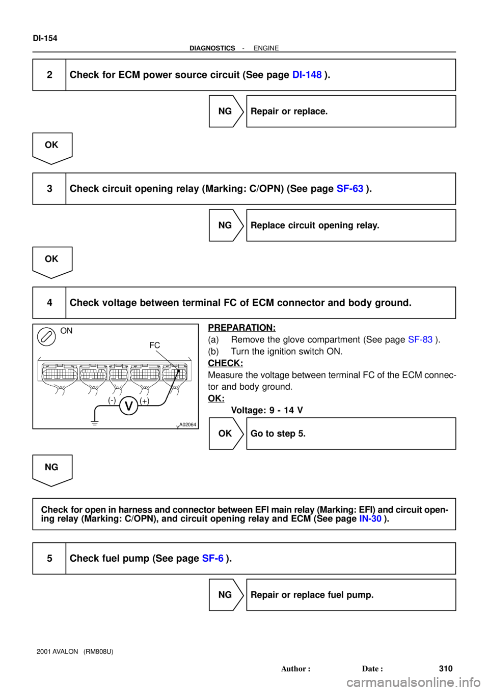
4 Check voltage between terminal FC of ECM connector and body ground.
PREPARATION:
(a) Remove the glove compartment (See page SF-83).
(b) Turn the ignition switch ON.
CHECK:
Measure the voltage between terminal FC of the ECM connec-
tor and body ground.
OK:
Voltage: 9 - 14 V
OK Go to step 5.
NG
Check for open in harness and connector between EFI main relay (Marking: EFI) and circuit open-
ing relay (Marking: C/OPN), and circuit opening relay and ECM (See page IN-30).
5 Check fuel pump (See page SF-6).
NG Repair or replace fuel pump.
Page 901 of 1897
A02042
ON
FC
- DIAGNOSTICSENGINE
DI-155
311 Author�: Date�:
2001 AVALON (RM808U)
OK
6 Check for open in harness and connector between circuit opening relay (Mark-
ing: C/OPN) and fuel pump, and fuel pump and body ground
(See page IN-30).
NG Repair or replace harness or connector.
OK
Check and replace ECM (See page IN-30).
OBD II scan tool (excluding TOYOTA hand-held tester):
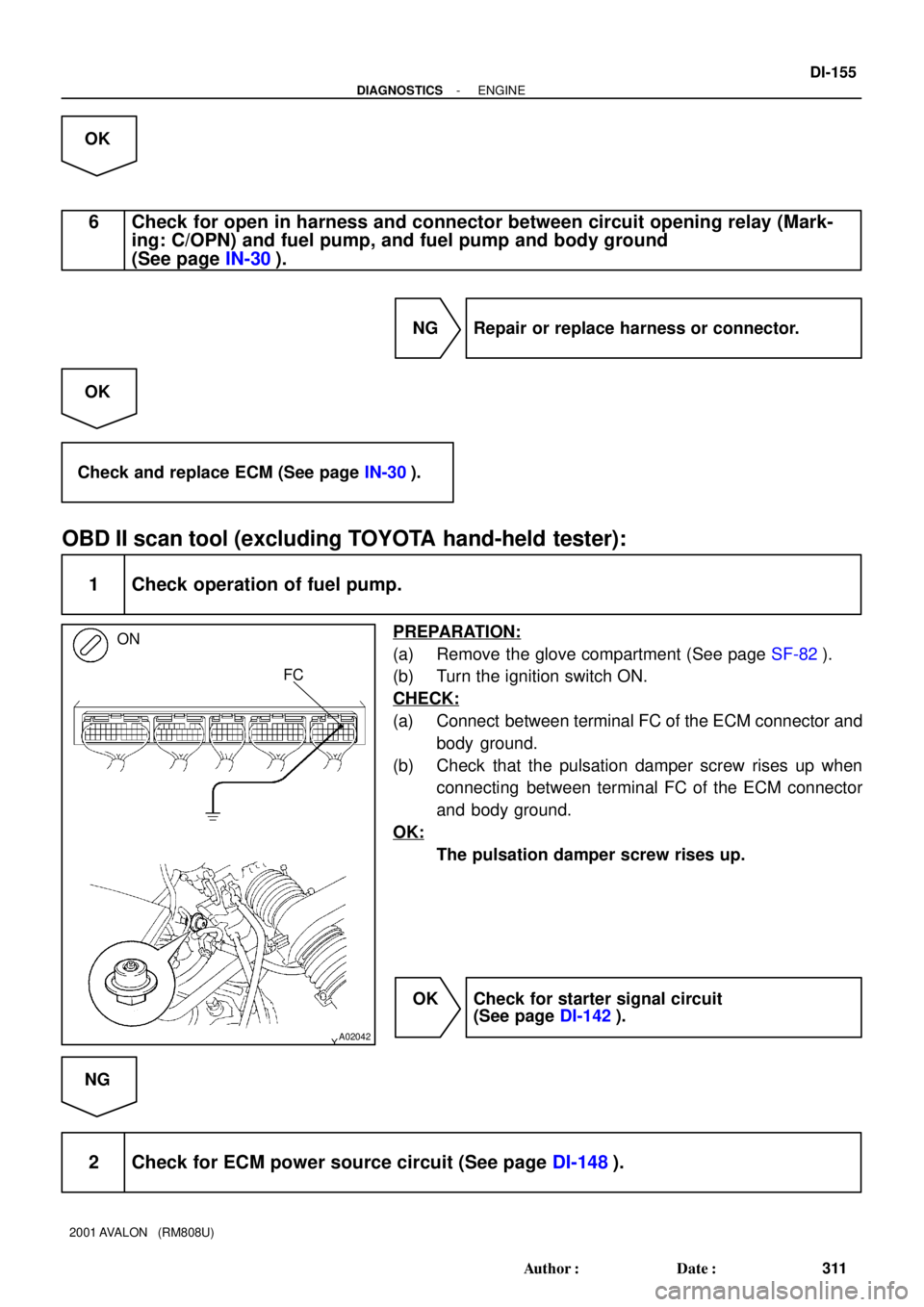
1 Check operation of fuel pump.
PREPARATION:
(a) Remove the glove compartment (See page SF-82).
(b) Turn the ignition switch ON.
CHECK:
(a) Connect between terminal FC of the ECM connector and
body ground.
(b) Check that the pulsation damper screw rises up when
connecting between terminal FC of the ECM connector
and body ground.
OK:
The pulsation damper screw rises up.
OK Check for starter signal circuit
(See page DI-142).
NG
2 Check for ECM power source circuit (See page DI-148).
Page 902 of 1897
A02064
ON
FC
(+) (-)
DI-156
- DIAGNOSTICSENGINE
312 Author�: Date�:
2001 AVALON (RM808U)
NG Repair or replace.
OK
3 Check circuit opening relay (Marking: C/OPN) (See page SF-63).
NG Replace circuit opening relay.
OK
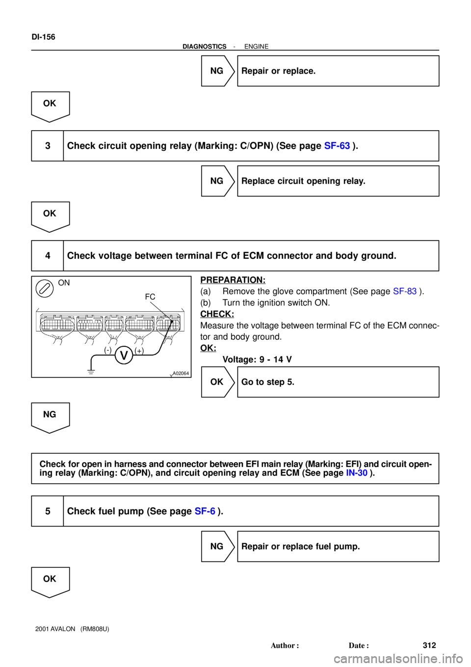
4 Check voltage between terminal FC of ECM connector and body ground.
PREPARATION:
(a) Remove the glove compartment (See page SF-83).
(b) Turn the ignition switch ON.
CHECK:
Measure the voltage between terminal FC of the ECM connec-
tor and body ground.
OK:
Voltage: 9 - 14 V
OK Go to step 5.
NG
Check for open in harness and connector between EFI main relay (Marking: EFI) and circuit open-
ing relay (Marking: C/OPN), and circuit opening relay and ECM (See page IN-30).
5 Check fuel pump (See page SF-6).
NG Repair or replace fuel pump.
OK
Page 903 of 1897
- DIAGNOSTICSENGINE
DI-157
313 Author�: Date�:
2001 AVALON (RM808U)
6 Check for open in harness and connector between circuit opening relay (Mark-
ing: C/OPN) and fuel pump, and fuel pump and body ground
(See page IN-30).
NG Repair or replace harness or connector.
OK
Check and replace ECM (See page IN-30).
Page 930 of 1897
DI-46
- DIAGNOSTICSENGINE
202 Author�: Date�:
2001 AVALON (RM808U)
3 Check for open and short in harness and connector between ECM and A/F sen-
sor (bank 1, 2 sensor 1) (See page IN-30).
NG Repair or replace harness or connector.
OK
4 Check resistance of A/F sensor heater (bank 1, 2 sensor 1) (See page SF-79).
NG Replace A/F sensor.
OK
5 Check air induction system (See page SF-1).
NG Repair or replace.
OK
6 Check fuel pressure (See page SF-6).
NG Check and repair fuel pump, pressure regulator,
fuel pipe line and filter (See page SF-1).
OK
7 Check injector injection (See page SF-23).
NG Replace injector.
OK
Page 941 of 1897
FI6588
FI6538
A00064
10 V
/Division10 V
/Division
GND GND
100 msec./Division (Idling)1 msec./Division (Idling)
Injection duration
(Magnification) Injector Signal Waveform
DI-62
- DIAGNOSTICSENGINE
218 Author�: Date�:
2001 AVALON (RM808U)
Reference: INSPECTION USING OSCILLOSCOPE
With the engine idling, check the waveform between terminals #10 - #60 and E01 of the ECM connector.
HINT:
The correct waveform is as shown.
OK Go to step 5.
NG
4 Check resistance of injector of misfiring cylinder (See page SF-19).
NG Replace injector.
OK
Check for open and short in harness and con-
nector between injector and ECM (See page
IN-30).
5 Check fuel pressure (See page SF-6).
NG Check and repair fuel pump, fuel pipe line and
filter (See page SF-1).

(NE Signal) MAINMREL
IGSW
ST DI-152
- DIAGNOSTICS")


1 msec./Division (Idling)
Injection duration
(Magnification) Injector Signal Waveform
DI-62
- DIAGNOSTICSENGINE
218")