Page 988 of 1897
- DIAGNOSTICSENGINE
DI-109
265 Author�: Date�:
2001 AVALON (RM808U)
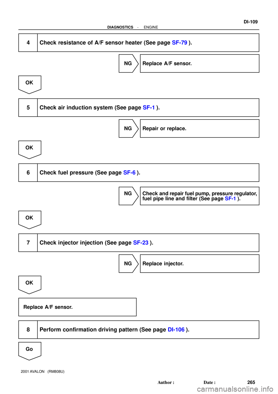
4 Check resistance of A/F sensor heater (See page SF-79).
NG Replace A/F sensor.
OK
5 Check air induction system (See page SF-1).
NG Repair or replace.
OK
6 Check fuel pressure (See page SF-6).
NG Check and repair fuel pump, pressure regulator,
fuel pipe line and filter (See page SF-1).
OK
7 Check injector injection (See page SF-23).
NG Replace injector.
OK
Replace A/F sensor.
8 Perform confirmation driving pattern (See page DI-106).
Go
Page 992 of 1897
- DIAGNOSTICSENGINE
DI-1 13
269 Author�: Date�:
2001 AVALON (RM808U)
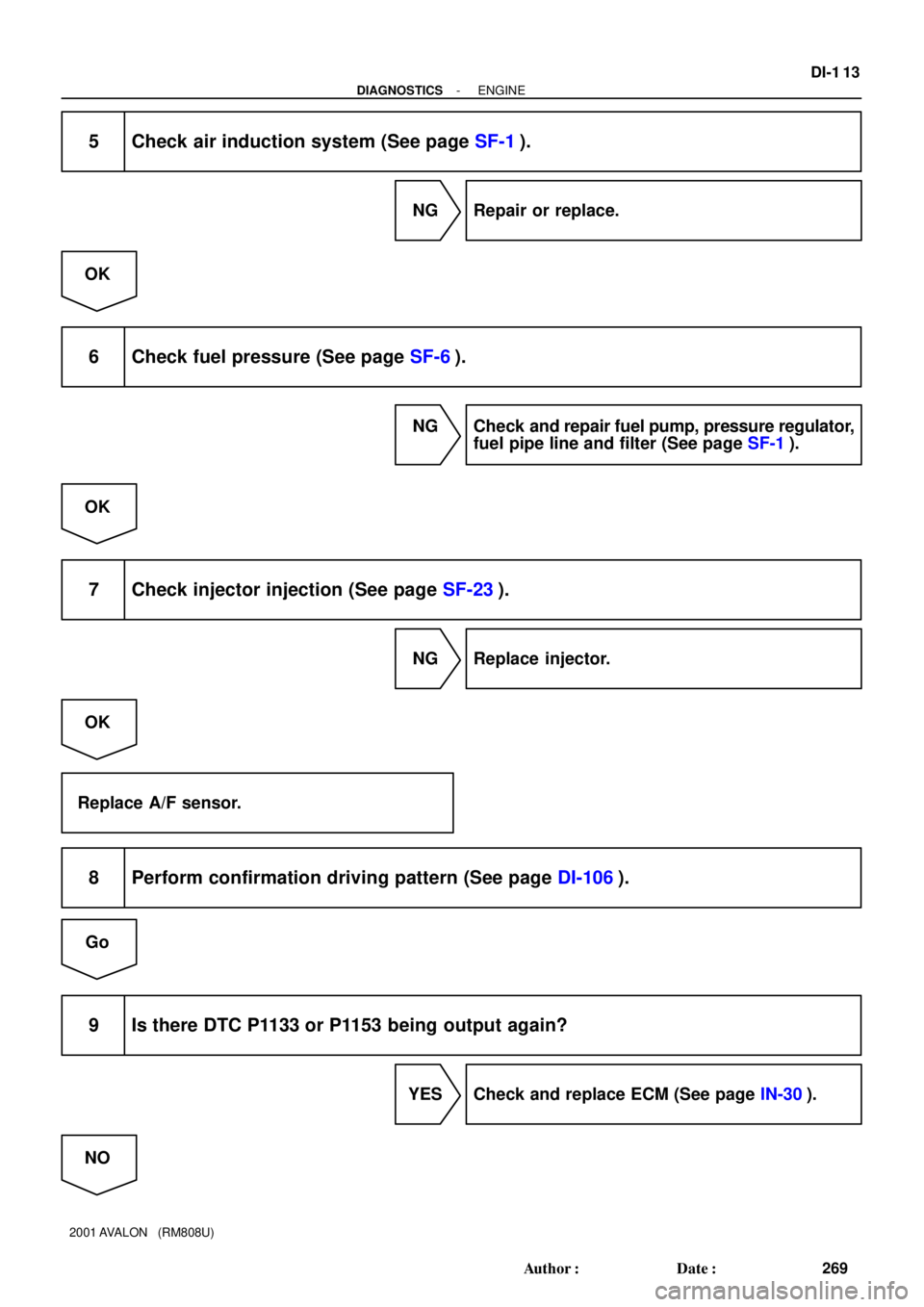
5 Check air induction system (See page SF-1).
NG Repair or replace.
OK
6 Check fuel pressure (See page SF-6).
NG Check and repair fuel pump, pressure regulator,
fuel pipe line and filter (See page SF-1).
OK
7 Check injector injection (See page SF-23).
NG Replace injector.
OK
Replace A/F sensor.
8 Perform confirmation driving pattern (See page DI-106).
Go
9 Is there DTC P1133 or P1153 being output again?
YES Check and replace ECM (See page IN-30).
NO
Page 1023 of 1897
- DIAGNOSTICSENGINE
DI-55
211 Author�: Date�:
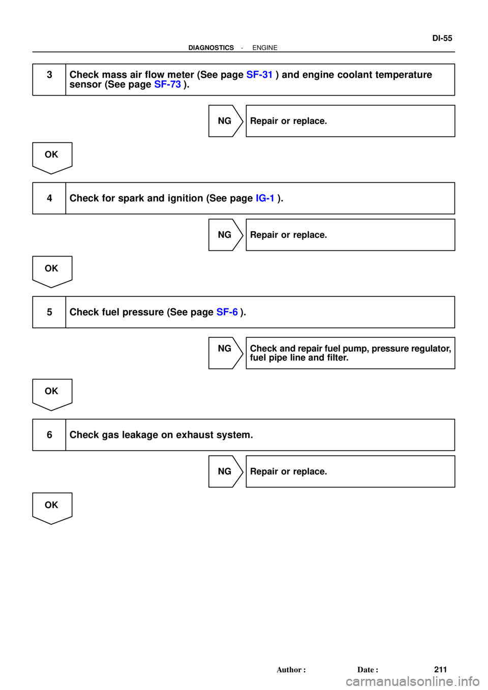
3 Check mass air flow meter (See page SF-31) and engine coolant temperature
sensor (See page SF-73).
NG Repair or replace.
OK
4 Check for spark and ignition (See page IG-1).
NG Repair or replace.
OK
5 Check fuel pressure (See page SF-6).
NG Check and repair fuel pump, pressure regulator,
fuel pipe line and filter.
OK
6 Check gas leakage on exhaust system.
NG Repair or replace.
OK
Page 1044 of 1897

OK
6 Check ignition timing.
PREPARATION:
(a) Warm up engine to normal operating te")
A00209
DLC1
TE1
E1
SST
DLC1
P12915
P12952
A02330
DI-10
- DIAGNOSTICSENGINE
166 Author�: Date�:
2001 AVALON (RM808U)
OK
6 Check ignition timing.
PREPARATION:
(a) Warm up engine to normal operating temperature.
(b) Switch off all the accessories.
(c) Switch off the A/C.
(d) Shift the transmission into the N position.
(e) Keep the engine speed at idle.
(f) Using SST, connect terminals TE1 and E1 of the DLC1.
SST 09843-18020
(g) Using a timing light, connect the tester to check wire.
CHECK:
Check the ignition timing.
OK:
Ignition timing: 10° BTDC at idle
NG Proceed to page IG-1, and continue to trouble-
shoot.
OK
Proceed to problem symptoms table on page
DI-22.
7 Check fuel pressure.
PREPARATION:
(a) Be sure that enough fuel is in the tank.
(b) Connect the TOYOTA hand-held tester to the DLC3.
(c) Turn the ignition switch ON and push TOYOTA hand-held
tester main switch ON.
(d) Use the ACTIVE TEST mode to operate the fuel pump.
(e) If you have no TOYOTA hand-held tester, connect the
positive (+) and negative (-) leads from the battery to the
fuel pump connector (See page SF-6).
CHECK:
Check that the pulsation damper screw rises up when the fuel
pump operates.
NG Proceed to page SF-6, and continue to trouble-
shoot.
Page 1046 of 1897
SHORT FT #2
Short-term Fuel Trim Bank 20 ± 20 %
LONG FT #2Long-term Fuel Trim Bank 20 ± 20 %
ENGINE SPDEngine SpeedIdling: 650 - 7")
DI-12
- DIAGNOSTICSENGINE
168 Author�: Date�:
2001 AVALON (RM808U)SHORT FT #2
Short-term Fuel Trim Bank 20 ± 20 %
LONG FT #2Long-term Fuel Trim Bank 20 ± 20 %
ENGINE SPDEngine SpeedIdling: 650 - 750 rpm
VEHICLE SPDVehicle SpeedVehicle stopped: 0 km/h (0 mph)
IGN ADVANCEIgnition Advance: Ignition Timing of Cylinder No.1Idling: BTDC 10 - 25.0°
INTAKE AIRIntake Air Temp. Sensor ValueEquivalent to Ambient Temp.
MAFAir Flow Rate Through Mass Air Flow Meter
Idling: 3.3 - 4.7 gm/sec.
Racing without load (2,500 rpm):
10.4 - 15.4 gm/sec.
THROTTLE POSVoltage Output of Throttle Position Sensor Calcu-
lated as a percentage: 0 V "0 %, 5 V "100 %Throttle valve fully closed: 7 - 11 %
Throttle valve fully open: 65 - 75 %
O2FT B1 S1Oxygen Sensor Fuel Trim Bank 1 Sensor 1
(Same as SHORT FT #1)0 ± 20 %
O2S B1 S2Voltage Output of Oxygen Sensor Bank 1 Sensor
2Driving 50 km/h (31 mph): 0.05 - 0.95 V
O2FT B2 S1Oxygen Sensor Fuel Trim Bank 2 Sensor 1
(Same as SHORT FT #2)0 ± 20 %
A/FS B1 S1Voltage Output of A/F Sensor Bank 1 Sensor 1Idling: 2.8 - 3.8 V
A/FS B2 S1Voltage Output of A/F Sensor Bank 2 Sensor 1Idling: 2.8 - 3.8 V
A/FFT B1 S1A/F Sensor Fuel Trim Bank 1 Sensor 1
(Same as SHORT FT #1)0 ± 20 %
A/FFT B2 S1A/F Sensor Fuel Trim Bank 2 Sensor 1
(Same as SHORT FT #1)0 ± 20 %
*: If no conditions are specifically stated for ºldlingº, it means the shift lever is at N or P position, the A/C switch
is OFF and all accessory switches are OFF.
(b) TOYOTA Enhanced Signals.
TOYOTA hand-held tester displayMeasurement ItemNormal Condition*
MISFIRE RPMEngine RPM for first misfire rangeMisfire 0: 0 rpm
MISFIRE LOADEngine load for first misfire rangeMisfire 0: 0 g/r
INJECTORFuel injection time for cylinder No.1Idling: 1.6 - 2.9 ms
IAC DUTY RATIOIntake Air Control Valve Duty Ratio
Opening ratio rotary solenoid type IAC valveIdling: 27 - 47 %
STARTER SIGStarter SignalCranking: ON
CTP SIGClosed Throttle Position SignalThrottle fully closed: ON
A/C SIGA/C Switch SignalA/C ON: ON
PNP SWPark/Neutral Position Switch SignalP or N position: ON
ELCTRCL LOAD SIGElectrical Load SignalDefogger switch ON: ON
STOP LIGHT SWStop Light Switch SignalStop light switch ON: ON
PS OIL PRESS SWPower Steering Oil Pressure Switch SignalTurn steering wheel: ON
FC IDLFuel Cut Idle: Fuel cut when throttle valve fully
closed, during decelerationFuel cut operating: ON
FC TAUFuel Cut TAU: Fuel cut during very light loadFuel cut operating: ON
CYL#1 - CYL#6Abnormal revolution variation for each cylinder0 %
IGNITIONTotal number of ignition for every 1,000 revolu-
tions0 - 3,000
INTAKE CTRL VSVIntake Air Control Valve VSV SignalVSV operating: ON
A/C CUT SIGA/C Cut SignalA/C S/W OFF: ON
FUEL PUMPFuel Pump SignalIdling: ON
Page 1048 of 1897

PROBLEM SYMPTOMS TABLE
SymptomSuspect AreaSee page
Engine does not crank (Does not start)15.Starter
16.Starter relayST-18")
DI07E-09
DI-22
- DIAGNOSTICSENGINE
178 Author�: Date�:
2001 AVALON (RM808U)
PROBLEM SYMPTOMS TABLE
SymptomSuspect AreaSee page
Engine does not crank (Does not start)15.Starter
16.Starter relayST-18
ST-20
No initial combustion (Does not start)
1. ECM power source circuit
2. Fuel pump control circuit
3. ECMDI-148
DI-152
IN-30
No complete combustion (Does not start)1. Fuel pump control circuitDI-152
Engine cranks normally (Difficult to start)
1. Starter signal circuit
2. Fuel pump control circuit
3. CompressionDI-142
DI-152
EM-3
Cold engine (Difficult to start)1. Starter signal circuit
2. Fuel pump control circuitDI-142
DI-152
Hot engine (Difficult to start)1. Starter signal circuit
2. Fuel pump control circuitDI-142
DI-152
High engine idle speed (Poor idling)1. A/C signal circuit (Compressor circuit)
2. ECM power source circuitDI-824
DI-148
Low engine idle speed (Poor idling)1. A/C signal circuit (Compressor circuit)
2. Fuel pump control circuitDI-824
DI-152
Rough idling (Poor idling)1. Compression
2. Fuel pump control circuitEM-3
DI-152
Hunting (Poor idling)1. ECM power source circuit
2. Fuel pump control circuitDI-148
DI-152
Hesitation/Poor acceleration (Poor driveability)1. Fuel pump control circuit
2. A/T faultyDI-152
DI-158
Surging (Poor driveability)1. Fuel pump control circuitDI-152
Soon after starting (Engine stall)1. Fuel pump control circuitDI-152
During A/C operation (Engine stall)1. A/C signal circuit (Compressor circuit)
2. ECMDI-824
IN-30
Unable to refuel/Difficult to refuel1. ORVR systemEC-6
Page 1370 of 1897

(j) Disconnect the fuel inlet hose from the fuel filter.
CAUTION:
Perform disconne")
S04497
A10833
Bracket
P18775
A07430
- ENGINE MECHANICALENGINE UNIT
EM-73
1057 Author�: Date�:
2001 AVALON (RM808U)
(j) Disconnect the fuel inlet hose from the fuel filter.
CAUTION:
Perform disconnecting operation of the fuel tube connec-
tor (quick type) after observing the precautions (See page
SF-1).
(k) Disconnect the EVAP hose assembly from the pipe on the
emission control valve set.
(l) Disconnect the 2 vacuum hoses from the vacuum tank for
the ACIS.
13. DISCONNECT ENGINE WIRE FROM CABIN
(a) Remove the glove compartment.
(b) Disconnect the 5 ECM connectors.
(c) Disconnect the grommet from the cowl panel, and pull out
the engine wire.
14. REMOVE DRIVE SHAFTS (See page SA-16)
15. DISCONNECT A/C COMPRESSOR FROM ENGINE
(a) Disconnect the A/C compressor connector.
(b) Remove the drive belt.
(c) Remove the 5 bolts, nut and drive belt adjusting bar
bracket.
(d) Disconnect the A/C compressor from the engine.
16. DISCONNECT TRANSAXLE CONTROL CABLE FROM
TRANSAXLE
17. DISCONNECT PS PUMP FROM ENGINE
(a) Remove the 2 nuts, and disconnect the PS pressure tube
from the No.1 engine hanger.
(b) Loosen the 2 bolts, and remove the drive belt.
(c) Remove the 2 bolts, and disconnect the PS pump from
the engine.
18. DISCONNECT TRANSAXLE FROM LH ENGINE
MOUNTING INSULATOR
Remove the 4 bolts holding the transaxle to the mounting insu-
lator.
Page 1423 of 1897

5. PROBLEM SYMPTOMS TABLE
The suspected circuits or parts for each problem symptom are shown in")
- INTRODUCTIONHOW TO TROUBLESHOOT ECU CONTROLLED
SYSTEMSIN-27
27 Author�: Date�:
2001 AVALON (RM808U)
5. PROBLEM SYMPTOMS TABLE
The suspected circuits or parts for each problem symptom are shown in the table below. Use this table to
troubleshoot the problem when a ºNormalº code is displayed in the diagnostic trouble code check but the
problem is still occurring. Numbers in the table indicate the inspection order in which the circuits or parts
should be checked.
HINT:
When the problem is not detected by the diagnostic system even though the problem symptom is present,
it is considered that the problem is occurring outside the detection range of the diagnostic system, or that
the problem is occurring in a system other than the diagnostic system.
Symptom
Suspect AreaSee page
Engine does not crank (Does not start)
No initial combustion (Does not start)
No complete combustion (Does not start)1. Starter and starter relay
1. ECM power source circuit
2. Fuel pump control circuit
3. Engine control module (ECM)
1. Starter signal circuit
2. Fuel pump control circuit1. Fuel pump control circuitDI-147
DI-151
IN-29
PROBLEM SYMPTOMS TABLE
1. Compression
2. Fuel pump control circuit 1. A/C signal circuit
2. Fuel pump control circuit 1. A/C signal circuit (Compressor circuit)
2. ECM power source circuit 1. Starter signal circuit
2. Fuel pump control circuit1. Starter signal circuit
2. Fuel pump control circuit
3. Compression
idling) High engine idle speed (Poor idling) Hot engine Cold engine (Difficult to start)Engine cranks normally (Difficult to start)
AC-88 DI-144
DI-151
EM-3 DI-151
� Problem Symptom� Page
Indicates the page where the flow chart for each circuit
is located.
� Circuit Inspection, Inspection Order
Indicates the circuit which needs to be checked for each problem
symptom. Check in the order indicated by the numbers.
� Circuit or Part Name
Indicates the circuit or part which needs to be checked.
ST-2
ST-17
DI-144
DI-151
DI-144
DI-151