Page 100 of 1897
Q06530
Q10038
D07216
Q10037
- AUTOMATIC TRANSAXLEAUTOMATIC TRANSAXLE UNIT
AX-37
1327 Author�: Date�:
2001 AVALON (RM808U)
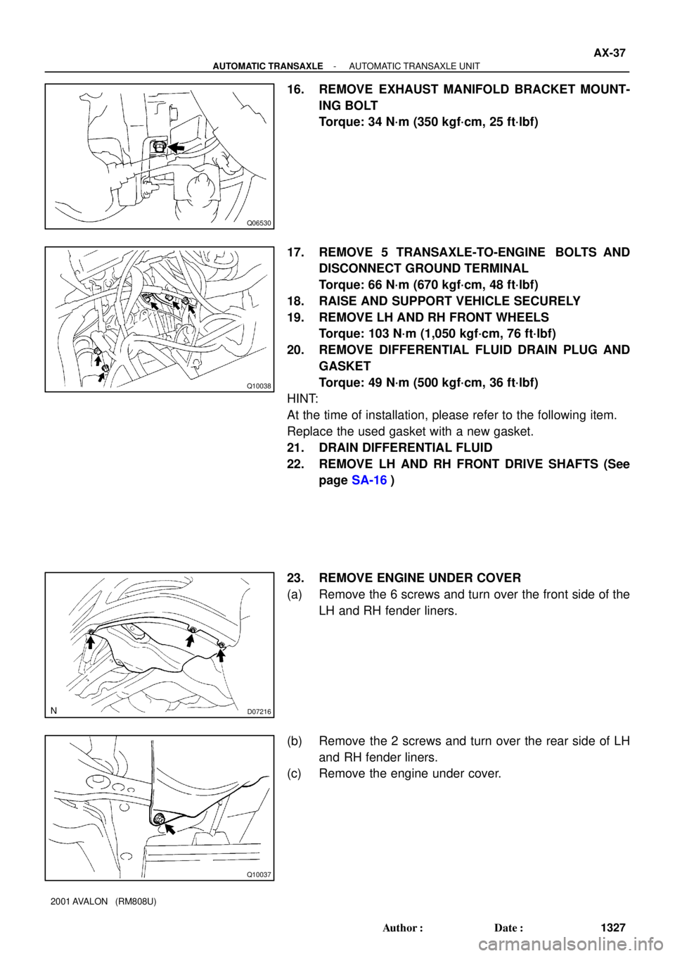
16. REMOVE EXHAUST MANIFOLD BRACKET MOUNT-
ING BOLT
Torque: 34 N´m (350 kgf´cm, 25 ft´lbf)
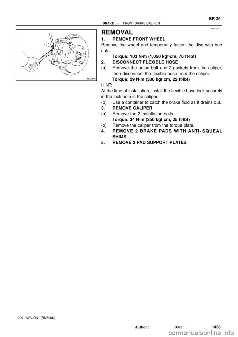
17. REMOVE 5 TRANSAXLE-TO-ENGINE BOLTS AND
DISCONNECT GROUND TERMINAL
Torque: 66 N´m (670 kgf´cm, 48 ft´lbf)
18. RAISE AND SUPPORT VEHICLE SECURELY
19. REMOVE LH AND RH FRONT WHEELS
Torque: 103 N´m (1,050 kgf´cm, 76 ft´lbf)
20. REMOVE DIFFERENTIAL FLUID DRAIN PLUG AND
GASKET
Torque: 49 N´m (500 kgf´cm, 36 ft´lbf)
HINT:
At the time of installation, please refer to the following item.
Replace the used gasket with a new gasket.
21. DRAIN DIFFERENTIAL FLUID
22. REMOVE LH AND RH FRONT DRIVE SHAFTS (See
page SA-16)
23. REMOVE ENGINE UNDER COVER
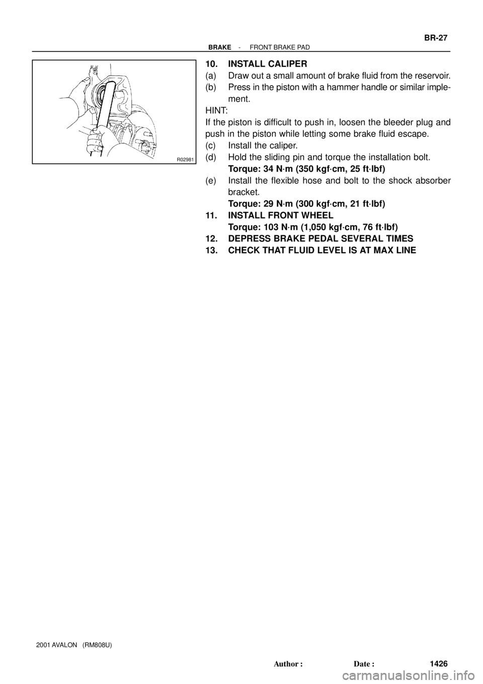
(a) Remove the 6 screws and turn over the front side of the
LH and RH fender liners.
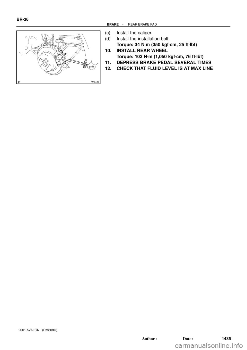
(b) Remove the 2 screws and turn over the rear side of LH
and RH fender liners.
(c) Remove the engine under cover.
Page 404 of 1897
BO41D-01
H15909
H12121
2 Clips
Clip
- BODYLUGGAGE COMPARTMENT DOOR AND HINGE
BO-31
1816 Author�: Date�:
2001 AVALON (RM808U)
REMOVAL
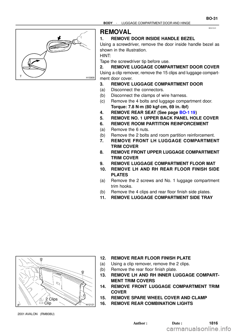
1. REMOVE DOOR INSIDE HANDLE BEZEL
Using a screwdriver, remove the door inside handle bezel as
shown in the illustration.
HINT:
Tape the screwdriver tip before use.
2. REMOVE LUGGAGE COMPARTMENT DOOR COVER
Using a clip remover, remove the 15 clips and luggage compart-
ment door cover.
3. REMOVE LUGGAGE COMPARTMENT DOOR
(a) Disconnect the connectors.
(b) Disconnect the clamps of wire harness.
(c) Remove the 4 bolts and luggage compartment door.
Torque: 7.8 N´m (80 kgf´cm, 69 in.´lbf)
4. REMOVE REAR SEAT (See page BO-1 19)
5. REMOVE NO. 1 UPPER BACK PANEL HOLE COVER
6. REMOVE ROOM PARTITION REINFORCEMENT
(a) Remove the 6 nuts.
(b) Remove the 2 bolts and room partition reinforcement.
7. REMOVE FRONT LH LUGGAGE COMPARTMENT
TRIM COVER
8. REMOVE FRONT UPPER LUGGAGE COMPARTMENT
TRIM COVER
9. REMOVE LUGGAGE COMPARTMENT FLOOR MAT
10. REMOVE LH AND RH REAR FLOOR FINISH SIDE
PLATES
(a) Remove the 2 screws and No. 1 luggage compartment
trim hooks.
(b) Remove the 4 clips and rear floor finish side plates.
11. REMOVE LUGGAGE COMPARTMENT SIDE TRAY
12. REMOVE REAR FLOOR FINISH PLATE
(a) Using a clip remover, remove the 2 clips.
(b) Remove the rear floor finish plate.
13. REMOVE LH AND RH INNER LUGGAGE COMPART-
MENT TRIM COVERS
14. REMOVE FRONT LUGGAGE COMPARTMENT TRIM
COVER
15. REMOVE SPARE WHEEL COVER AND CLAMP
16. REMOVE REAR COMBINATION LIGHTS
Page 517 of 1897
BR0L3-04
R02840
- BRAKEFRONT BRAKE CALIPER
BR-29
1428 Author�: Date�:
2001 AVALON (RM808U)
REMOVAL
1. REMOVE FRONT WHEEL
Remove the wheel and temporarily fasten the disc with hub
nuts.
Torque: 103 N´m (1,050 kgf´cm, 76 ft´lbf)
2. DISCONNECT FLEXIBLE HOSE
(a) Remove the union bolt and 2 gaskets from the caliper,
then disconnect the flexible hose from the caliper.
Torque: 29 N´m (300 kgf´cm, 22 ft´lbf)
HINT:
At the time of installation, install the flexible hose lock securely
in the lock hole in the caliper.
(b) Use a container to catch the brake fluid as it drains out.
3. REMOVE CALIPER
(a) Remove the 2 installation bolts.
Torque: 34 N´m (350 kgf´cm, 25 ft´lbf)
(b) Remove the caliper from the torque plate.
4. REMOVE 2 BRAKE PADS WITH ANTI- SQUEAL
SHIMS
5. REMOVE 2 PAD SUPPORT PLATES
Page 520 of 1897
R02981
- BRAKEFRONT BRAKE PAD
BR-27
1426 Author�: Date�:
2001 AVALON (RM808U)
10. INSTALL CALIPER
(a) Draw out a small amount of brake fluid from the reservoir.
(b) Press in the piston with a hammer handle or similar imple-
ment.
HINT:
If the piston is difficult to push in, loosen the bleeder plug and
push in the piston while letting some brake fluid escape.
(c) Install the caliper.
(d) Hold the sliding pin and torque the installation bolt.
Torque: 34 N´m (350 kgf´cm, 25 ft´lbf)
(e) Install the flexible hose and bolt to the shock absorber
bracket.
Torque: 29 N´m (300 kgf´cm, 21 ft´lbf)
11. INSTALL FRONT WHEEL
Torque: 103 N´m (1,050 kgf´cm, 76 ft´lbf)
12. DEPRESS BRAKE PEDAL SEVERAL TIMES
13. CHECK THAT FLUID LEVEL IS AT MAX LINE
Page 525 of 1897
BR0LH-03
W04053
R00309
BR3948
R00310
BR-44
- BRAKEPARKING BRAKE
1443 Author�: Date�:
2001 AVALON (RM808U)
DISASSEMBLY
1. REMOVE REAR WHEEL
Torque: 103 N´m (1,050 kgf´cm, 76 ft´lbf)
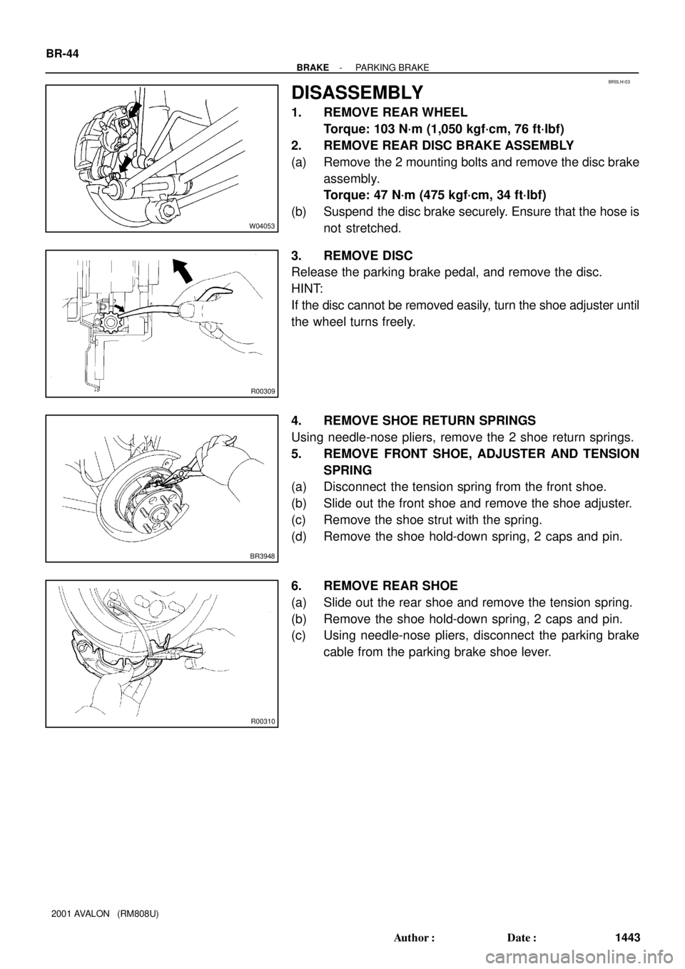
2. REMOVE REAR DISC BRAKE ASSEMBLY
(a) Remove the 2 mounting bolts and remove the disc brake
assembly.
Torque: 47 N´m (475 kgf´cm, 34 ft´lbf)
(b) Suspend the disc brake securely. Ensure that the hose is
not stretched.
3. REMOVE DISC
Release the parking brake pedal, and remove the disc.
HINT:
If the disc cannot be removed easily, turn the shoe adjuster until
the wheel turns freely.
4. REMOVE SHOE RETURN SPRINGS
Using needle-nose pliers, remove the 2 shoe return springs.
5. REMOVE FRONT SHOE, ADJUSTER AND TENSION
SPRING
(a) Disconnect the tension spring from the front shoe.
(b) Slide out the front shoe and remove the shoe adjuster.
(c) Remove the shoe strut with the spring.
(d) Remove the shoe hold-down spring, 2 caps and pin.
6. REMOVE REAR SHOE
(a) Slide out the rear shoe and remove the tension spring.
(b) Remove the shoe hold-down spring, 2 caps and pin.
(c) Using needle-nose pliers, disconnect the parking brake
cable from the parking brake shoe lever.
Page 540 of 1897
BR0LB-02
F09725
BR-38
- BRAKEREAR BRAKE CALIPER
1437 Author�: Date�:
2001 AVALON (RM808U)
REMOVAL
1. REMOVE REAR WHEEL
Remove the wheel and temporarily fasten the disc with hub
nuts.
Torque: 103 N´m (1,050 kgf´cm, 76 ft´lbf)
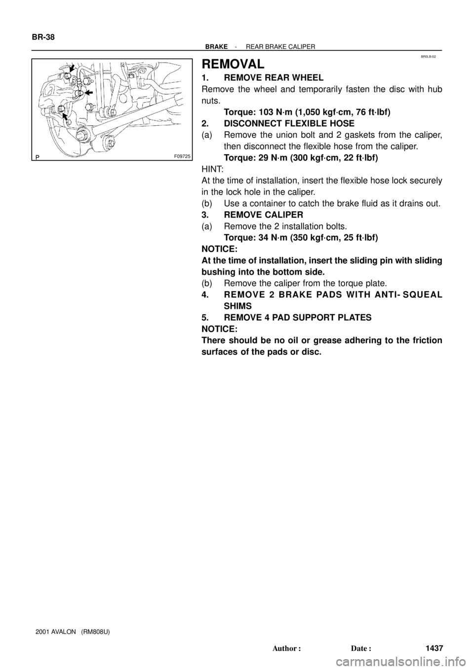
2. DISCONNECT FLEXIBLE HOSE
(a) Remove the union bolt and 2 gaskets from the caliper,
then disconnect the flexible hose from the caliper.
Torque: 29 N´m (300 kgf´cm, 22 ft´lbf)
HINT:
At the time of installation, insert the flexible hose lock securely
in the lock hole in the caliper.
(b) Use a container to catch the brake fluid as it drains out.
3. REMOVE CALIPER
(a) Remove the 2 installation bolts.
Torque: 34 N´m (350 kgf´cm, 25 ft´lbf)
NOTICE:
At the time of installation, insert the sliding pin with sliding
bushing into the bottom side.
(b) Remove the caliper from the torque plate.
4. REMOVE 2 BRAKE PADS WITH ANTI- SQUEAL
SHIMS
5. REMOVE 4 PAD SUPPORT PLATES
NOTICE:
There should be no oil or grease adhering to the friction
surfaces of the pads or disc.
Page 543 of 1897
F09723
BR-36
- BRAKEREAR BRAKE PAD
1435 Author�: Date�:
2001 AVALON (RM808U)
(c) Install the caliper.
(d) Install the installation bolt.
Torque: 34 N´m (350 kgf´cm, 25 ft´lbf)
10. INSTALL REAR WHEEL
Torque: 103 N´m (1,050 kgf´cm, 76 ft´lbf)
11. DEPRESS BRAKE PEDAL SEVERAL TIMES
12. CHECK THAT FLUID LEVEL IS AT MAX LINE
Page 779 of 1897
Q04700
Neutral Basic Line
BoltBolt
Groove DI-168
- DIAGNOSTICSAUTOMATIC TRANSAXLE
324 Author�: Date�:
2001 AVALON (RM808U)
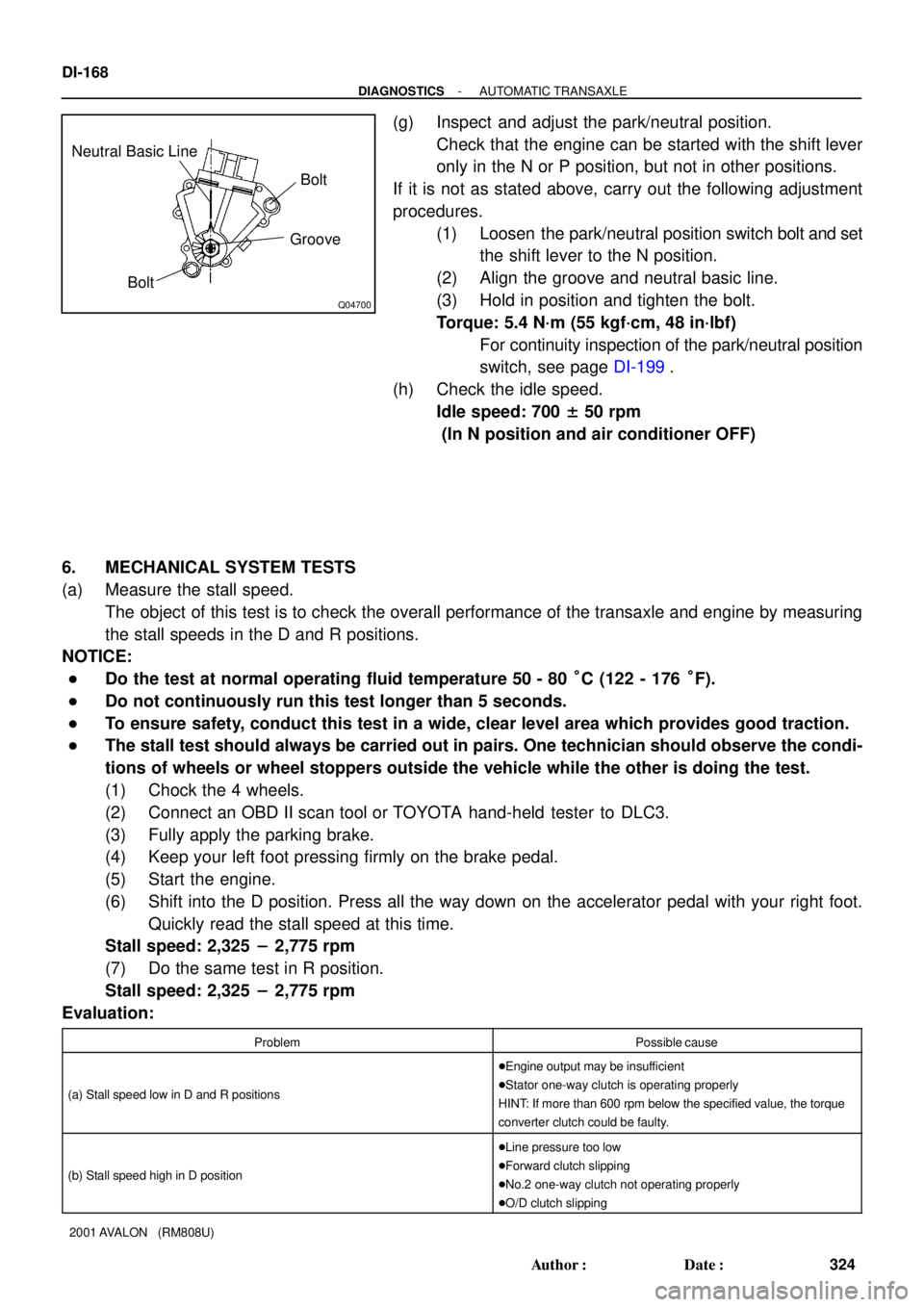
(g) Inspect and adjust the park/neutral position.
Check that the engine can be started with the shift lever
only in the N or P position, but not in other positions.
If it is not as stated above, carry out the following adjustment
procedures.
(1) Loosen the park/neutral position switch bolt and set
the shift lever to the N position.
(2) Align the groove and neutral basic line.
(3) Hold in position and tighten the bolt.
Torque: 5.4 N´m (55 kgf´cm, 48 in´lbf)
For continuity inspection of the park/neutral position
switch, see page DI-199.
(h) Check the idle speed.
Idle speed: 700 ± 50 rpm
(In N position and air conditioner OFF)
6. MECHANICAL SYSTEM TESTS
(a) Measure the stall speed.
The object of this test is to check the overall performance of the transaxle and engine by measuring
the stall speeds in the D and R positions.
NOTICE:
�Do the test at normal operating fluid temperature 50 - 80 °C (122 - 176 °F).
�Do not continuously run this test longer than 5 seconds.
�To ensure safety, conduct this test in a wide, clear level area which provides good traction.
�The stall test should always be carried out in pairs. One technician should observe the condi-
tions of wheels or wheel stoppers outside the vehicle while the other is doing the test.
(1) Chock the 4 wheels.
(2) Connect an OBD II scan tool or TOYOTA hand-held tester to DLC3.
(3) Fully apply the parking brake.
(4) Keep your left foot pressing firmly on the brake pedal.
(5) Start the engine.
(6) Shift into the D position. Press all the way down on the accelerator pedal with your right foot.
Quickly read the stall speed at this time.
Stall speed: 2,325 - 2,775 rpm
(7) Do the same test in R position.
Stall speed: 2,325 - 2,775 rpm
Evaluation:
ProblemPossible cause
(a) Stall speed low in D and R positions
�Engine output may be insufficient
�Stator one-way clutch is operating properly
HINT: If more than 600 rpm below the specified value, the torque
converter clutch could be faulty.
(b) Stall speed high in D position
�Line pressure too low
�Forward clutch slipping
�No.2 one-way clutch not operating properly
�O/D clutch slipping