Page 56 of 1897
AC28I-02
I12949I12950
I12965
N´m (kgf´cm, ft´lbf) : Specified torque
� Non-reusable part
Compressor oil ND-OIL 8 or equivalent
5.4 (55, 48 in.´lbf)
5.4 (55, 48 in.´lbf)
Discharge Hose
Liquid Tube� O-ringRadiator Upper SupportCondenser
Radiator Upper Support
Condenser
Dryer
Filter
Cap
12.3 (125, 9)
� O-ring
AC-52
- AIR CONDITIONINGCONDENSER
1974 Author�: Date�:
2001 AVALON (RM808U)
COMPONENTS
Page 60 of 1897
AC28K-02
I10090
10 mm (0.39 in.)
Hexagon
Wrench
Modulator
I10092
I10093
2 Layered
Part
I10091
Protrusion
I10094
AC-54
- AIR CONDITIONINGCONDENSER
1976 Author�: Date�:
2001 AVALON (RM808U)
REPLACEMENT
REPLACE DRIER FROM MODULATOR
(a) Using a hexagon wrench (10 mm, 0.39 in.), remove the
cap from the modulator.
(b) Remove the filter from the modulator.
(c) Using pliers, remove the drier.
(d) Insert a new drier into the modulator.
NOTICE:
�Do not remove the drier from a vinyl bag until insert-
ing it into the modulator.
�Install the drier with its 2 layered part faced upward to
the modulator.
(e) Insert the filter into the modulator.
NOTICE:
Install the filter with its protrusion faced downward to the
modulator.
(f) Install the cap to the modulator.
(1) Apply compressor oil to the O-rings and screw part
of the cap.
Compressor oil: ND-OIL 8 or equivalent
(2) Using a hexagon wrench (10 mm, 0.39 in.), install
the caps.
Torque: 12.3 N´m (125 kgf´cm, 9 ft´lbf)
Page 175 of 1897

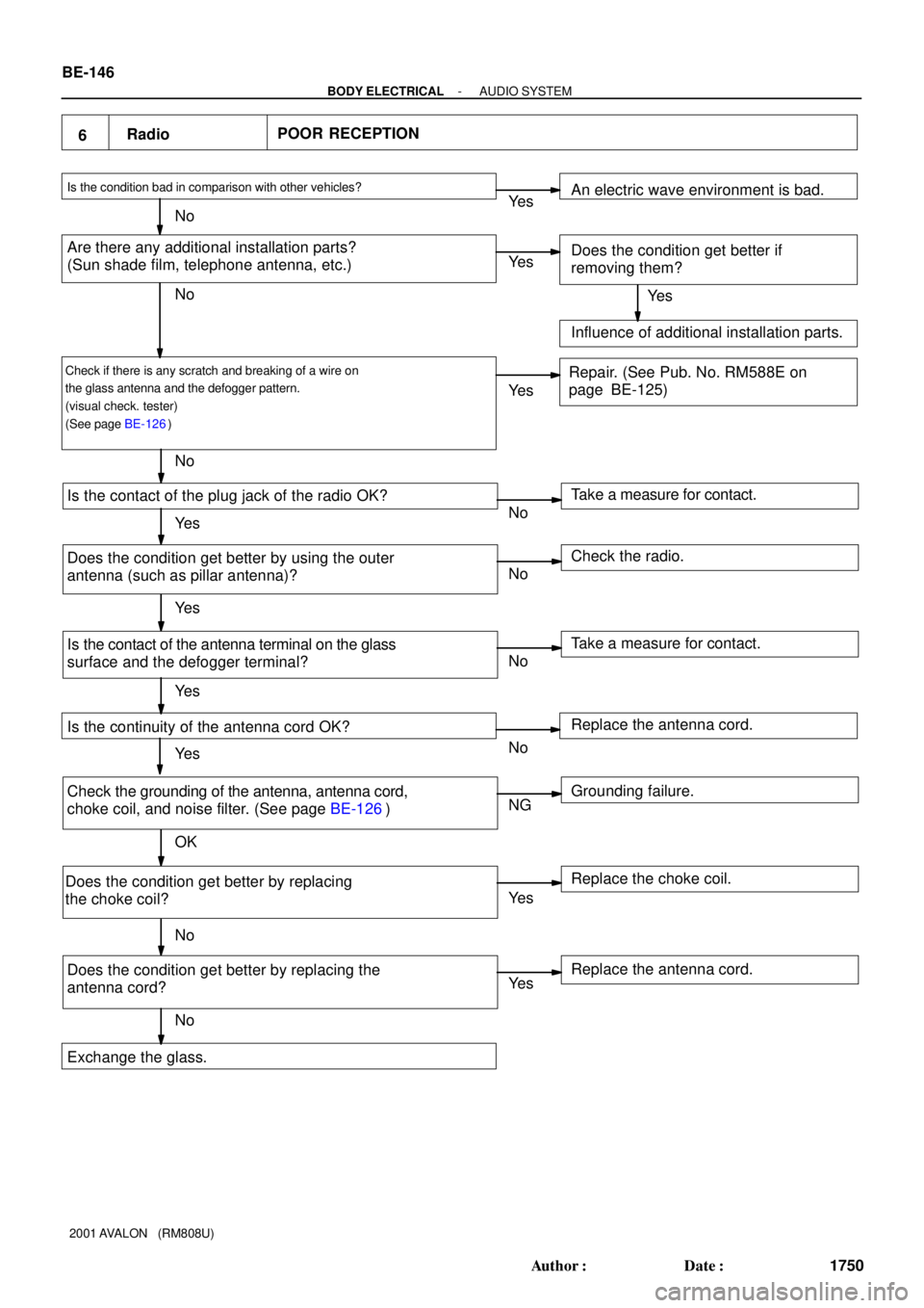
6RadioPOOR RECEPTION
Is the condition bad in comparison with other vehicles?
Are there any additional installation parts?
(Sun shade film, telephone antenna, etc.)
Check if there is any scratch and breaking of a wire on
the glass antenna and the defogger pattern.
(visual check. tester)
(See page BE-126)
Is the contact of the plug jack of the radio OK?
Does the condition get better by using the outer
antenna (such as pillar antenna)?
Is the contact of the antenna terminal on the glass
surface and the defogger terminal?
Is the continuity of the antenna cord OK?
Check the grounding of the antenna, antenna cord,
choke coil, and noise filter. (See page BE-126)
Does the condition get better by replacing
the choke coil?
Does the condition get better by replacing the
antenna cord?Take a measure for contact. An electric wave environment is bad.
Does the condition get better if
removing them?
Influence of additional installation parts.
Repair. (See Pub. No. RM588E on
page BE-125)
Check the radio.
Take a measure for contact.
Grounding failure. Replace the antenna cord.
Replace the choke coil.
Replace the antenna cord. Ye s
No
Exchange the glass.Ye s
Ye s
Ye s
Ye s
Ye s
Ye s
Ye s
Ye s No
No
No
NoNo
No
No
No
NG
OK
Ye s BE-146
- BODY ELECTRICALAUDIO SYSTEM
1750 Author�: Date�:
2001 AVALON (RM808U)
Page 187 of 1897

26 Noise NOISE OCCURS
No
Ye s
NG
OK Does the noise occur only in the radio?
Does the noise occur in a particular place?
Is there any additional installation part
around the glass imprinted antenna?
(Sun shade film, telephone antenna etc.)
Does the noise occur even pulling out the
antenna cord from the radio?
Does the noise occur even after pulling out the
antenna terminal on the glass surface?
Isn't there any adhesive (Butyl rubber)
stuck on the bases of the antenna
terminal, defogger terminal and bus bar?
Check the grounding of the antenna,
antenna cord, coke coil, and noise filter.
(See page BE-126) Does the noise occur even after pulling out
the defogger terminal?
Does the condition get better by replacing
the antenna cord.
Noise rediates directly to the antenna from the
generation source. Does the condition get better by replacing
the choke coil?
Replace the antenna cord. Replace the choke coil. Interfering noise from the defogger line
and choke coil.
Grounding failure. Failure of glass installation.
Must plane the butyl rubber. Noise mixing into the antenna cable. Check the radio. Influence of the film or the noise radiation
of the additional installation part. Does the noise stop by removing it? An electric environment.Refer to No.27. (It occurs in the cassette and CD.)
Ye s
Ye s
Ye s
Ye s
Ye s
Ye s
Ye s
Ye s No
No
No
No
No
No
No
No
BE-158
- BODY ELECTRICALAUDIO SYSTEM
1762 Author�: Date�:
2001 AVALON (RM808U)
Page 997 of 1897

A11669
14
3 2
B-R
L LG-B
L-Y
LG 1
4
2
43
21
43
21
43
21
43
2
Ignition Coil
with Igniter
No.2
No.3
No.4
No.5
No.6
Noise
Filter B-Y W-BB-W
GR
13 No.1B-W
B-W B-W B-W
B-WB-Y
B-Y B-Y B-Y B-Y B-Y
W-B
W-B
W-B
W-B W-B
1
B-W
B-WW-B
B-W
B-W
B-WW-B W-B W-B
B-W
W-BIGT1
IGF IGT2
IGT3
IGT4
IGT5
IGT6 11
12
13
14
15
16
25 E4
E4
E4
E4
E4
E4
E4ECM
Battery
EC ED
115
2B
B-O
2F 1C28
3
IG Switch72
14 IG2 Reray
2G
2C 2CIG2
AM2 72
1J B-O
7
6W-R
W-R4
IF1Engine Room J/B
Driver Side J/BB
Fusible
Link
Block
FL
Main 1F6 F7
B-W
1 B-Y
B-Y B-Y B-Y
W-B
DI-1 18
- DIAGNOSTICSENGINE
274 Author�: Date�:
2001 AVALON (RM808U)
WIRING DIAGRAM
INSPECTION PROCEDURE
HINT:
�If DTC P1300 is displayed, check No.1 ignition coil with igniter circuit.
�If DTC P1305 is displayed, check No.2 ignition coil with igniter circuit.
�If DTC P1310 is displayed, check No.3 ignition coil with igniter circuit.
�If DTC P1315 is displayed, check No.4 ignition coil with igniter circuit.
�If DTC P1320 is displayed, check No.5 ignition coil with igniter circuit.
�If DTC P1325 is displayed, check No.6 ignition coil with igniter circuit.
�If DTCs P1300, P1315 and P1325, are output simultaneously, IGF1 circuit may be open or short.
�If DTCs P1305, P1310 and P1320, are output simultaneously, IGF2 circuit may be open or short.
�Read freeze frame data using TOYOTA hand-held tester or OBD II scan tool. Because freeze frame
records the engine conditions when the malfunction is detected. When troubleshooting, it is useful for
determining whether the vehicle was running or stopped, the engine was warmed up or not, the air-fuel
ratio was lean or rich, etc. at the time of the malfunction.
1 Check spark plug and spark (See page DI-58).
Page 1007 of 1897

A02397
OCV Signal Waveform
1 m sec./Division5 V/
Division
GND
(A) (A) (A)
DI-128
- DIAGNOSTICSENGINE
284 Author�: Date�:
2001 AVALON (RM808U)
TOYOTA hand-held tester:
1 Check valve timing (See page EM-15).
NG Repair valve timing.
OK
2 Check operation of OCV.
PREPARATION:
(a) Start the engine and warmed it up.
(b) Connect the TOYOTA hand-held tester and select the VVT from the ACTIVE TEST menu.
CHECK:
Check the engine speed when operate the OCV by the TOYOTA hand-held tester.
OK:
OCV is OFF: Normal engine speed
OCV is ON: Rough idle or engine stall
OK VVT system is OK.*
*: DTCs P1349 and P1354 are also output after the foreign ob-
ject is caught in some part of the system in the engine oil and
the system returns to normal in a short time. As ECM controls
so that foreign objects are ejected, there is no problem about
VVT. There is also no problem since the oil filter should get the
foreign object in the engine oil.
NG
3 Check voltage between terminals OCV+ and OCV- of ECM connector.
Reference: INSPECTION USING OSCILLOSCOPE
Turn the ignition switch ON, and check the waveform between
terminals OCV+ and OCV- of the ECM connector.
HINT:
�The correct waveform is as shown.
�The waveform frequency (A) is lengthened as the engine
speed becomes higher.
NG Check and replace ECM (See page IN-30).
Page 1009 of 1897
DI-130
- DIAGNOSTICSENGINE
286 Author�: Date�:
2001 AVALON (RM808U)
CHECK:
Check whether or not DTC P1349/P1354 is stored (See page DI-3).
OK:
DTC P1349/P1354 is not stored.
OK VVT system is OK.*
*: DTCs P1349 and P1354 are also output after the foreign ob-
ject is caught in some part of the system in the engine oil and
the system returns to normal in a short time. As ECM controls
so that foreign objects are ejected, there is no problem about
VVT. There is also no problem since the oil filter should get the
foreign object in the engine oil.
NG
Replace ECM
OBD II scan tool (excluding TOYOTA hand-held tester):
1 Check valve timing (See page EM-15).
NG Repair valve timing.
OK
Page 1010 of 1897

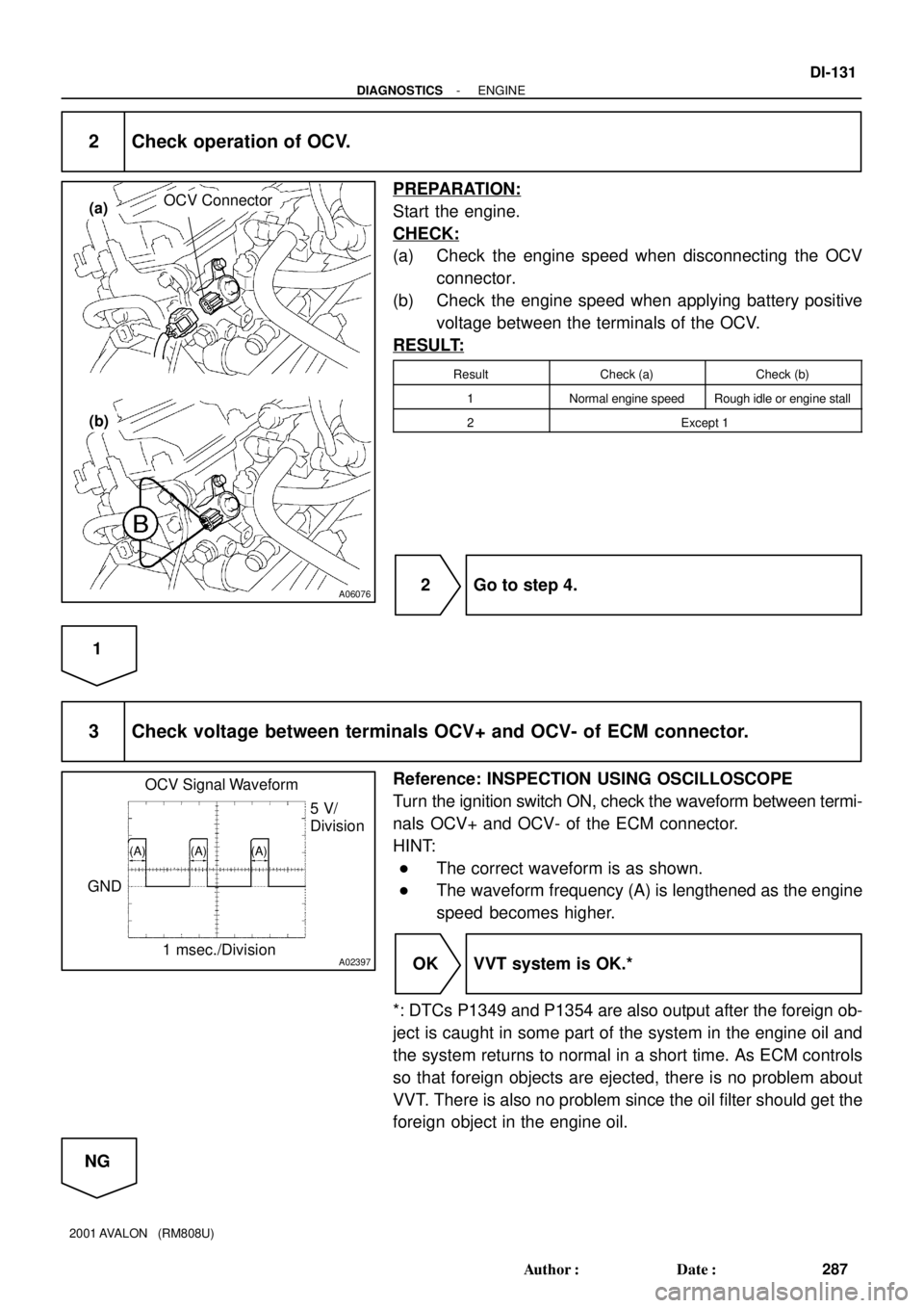
A06076
OCV Connector(a)
(b)
A02397
OCV Signal Waveform
1 msec./Division5 V/
Division
GND
(A) (A) (A)
- DIAGNOSTICSENGINE
DI-131
287 Author�: Date�:
2001 AVALON (RM808U)
2 Check operation of OCV.
PREPARATION:
Start the engine.
CHECK:
(a) Check the engine speed when disconnecting the OCV
connector.
(b) Check the engine speed when applying battery positive
voltage between the terminals of the OCV.
RESULT:
ResultCheck (a)Check (b)
1Normal engine speedRough idle or engine stall
2Except 1
2 Go to step 4.
1
3 Check voltage between terminals OCV+ and OCV- of ECM connector.
Reference: INSPECTION USING OSCILLOSCOPE
Turn the ignition switch ON, check the waveform between termi-
nals OCV+ and OCV- of the ECM connector.
HINT:
�The correct waveform is as shown.
�The waveform frequency (A) is lengthened as the engine
speed becomes higher.
OK VVT system is OK.*
*: DTCs P1349 and P1354 are also output after the foreign ob-
ject is caught in some part of the system in the engine oil and
the system returns to normal in a short time. As ECM controls
so that foreign objects are ejected, there is no problem about
VVT. There is also no problem since the oil filter should get the
foreign object in the engine oil.
NG