S04497
A07300
- ENGINE MECHANICALENGINE UNIT
EM-79
1063 Author�: Date�:
2001 AVALON (RM808U)
15. CONNECT ENGINE WIRE TO CABIN
(a) Push in the engine wire through the cowl panel. Install the
grommet.
(b) Connect the 5 engine ECM connectors.
(c) Install the glove compartment.
16. CONNECT CONNECTORS, CABLE, CLAMPS AND
HOSES
(a) Connect the noise filter connector on the LH fender
apron.
(b) Connect the generator connector and wire.
(c) Connect the starter connector and wire.
(d) Connect the 2 ground strap connectors to the RH fender
apron
(e) Connect the strap connector to the LH fender apron with
the bolt.
(f) Connect the ground cable to the battery body bracket.
(g) Connect the engine wire protector clamp to the battery
body bracket.
(h) Connect the engine wire clamp to the bracket on the RH
fender apron.
(i) Connect the brake booster vacuum hose to the throttle
body.
(j) Connect the engine coolant reservoir hose to the water
outlet.
(k) Connect the heater hose to the intake manifold.
(l) Connect the heater hose to the water inlet housing.
(m) Connect the fuel inlet hose to the fuel filter.
CAUTION:
Perform connecting operations of the fuel tube connector
(quick type) after observing the precautions.
(See page SF-1)
(n) Connect the EVAP hose assembly to the pipe on the
emission control valve set.
(o) Connect the 2 vacuum hoses to the vacuum tank for the
ACIS.
17. INSTALL FRONT EXHAUST PIPE
(a) Temporarily install 3 new gaskets and the front exhaust
pipe with the 2 bolts, 2 compression springs and 4 nuts.
(b) Tighten the 4 nuts holding the exhaust manifolds to the
front exhaust pipe.
Torque: 62 N´m (630 kgf´cm, 46 ft´lbf)
(c) Tighten the 2 bolts and 2 compression springs holding the
front exhaust pipe to the center exhaust pipe.
Torque: 43 N´m (440 kgf´cm, 32 ft´lbf)
S04497
A10833
Bracket
P18775
A07430
- ENGINE MECHANICALENGINE UNIT
EM-73
1057 Author�: Date�:
2001 AVALON (RM808U)
(j) Disconnect the fuel inlet hose from the fuel filter.
CAUTION:
Perform disconnecting operation of the fuel tube connec-
tor (quick type) after observing the precautions (See page
SF-1).
(k) Disconnect the EVAP hose assembly from the pipe on the
emission control valve set.
(l) Disconnect the 2 vacuum hoses from the vacuum tank for
the ACIS.
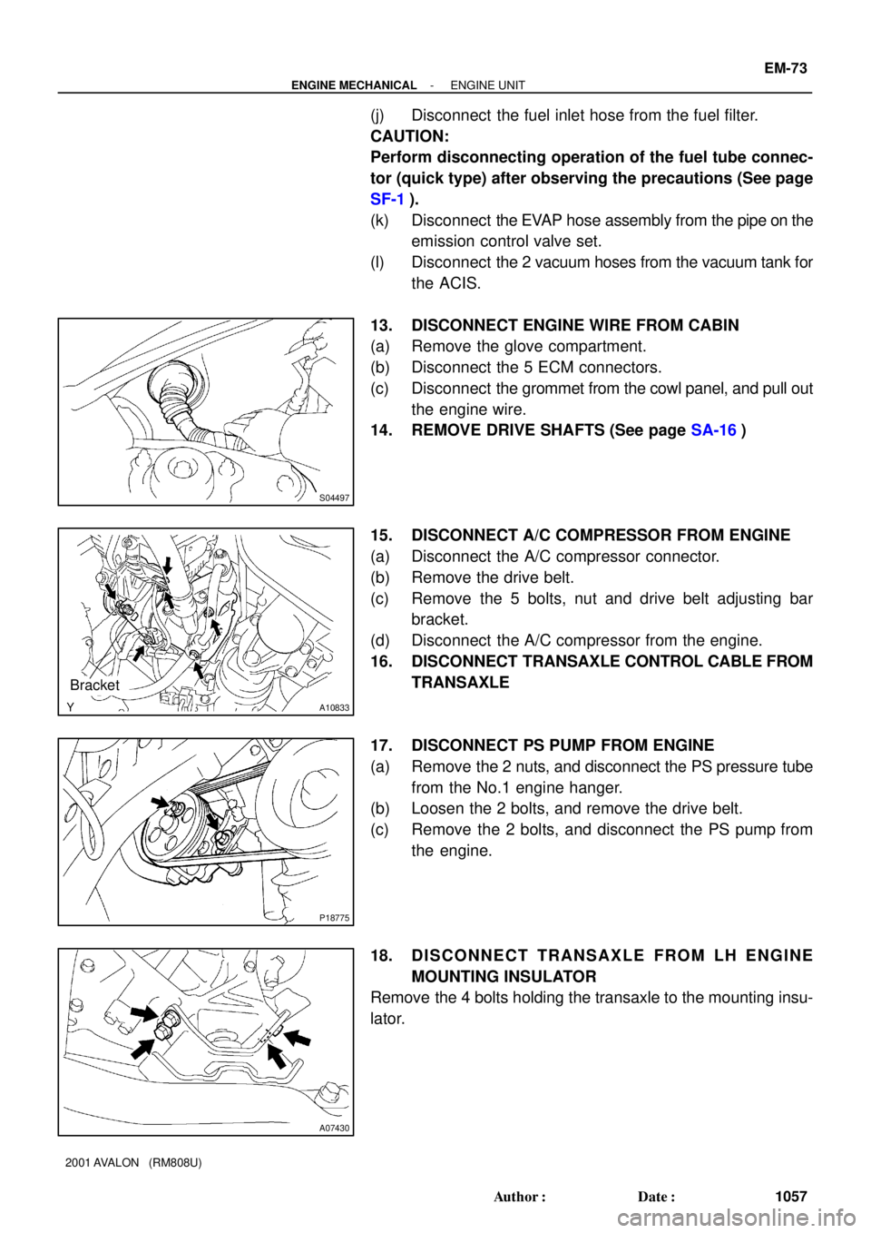
13. DISCONNECT ENGINE WIRE FROM CABIN
(a) Remove the glove compartment.
(b) Disconnect the 5 ECM connectors.
(c) Disconnect the grommet from the cowl panel, and pull out
the engine wire.
14. REMOVE DRIVE SHAFTS (See page SA-16)
15. DISCONNECT A/C COMPRESSOR FROM ENGINE
(a) Disconnect the A/C compressor connector.
(b) Remove the drive belt.
(c) Remove the 5 bolts, nut and drive belt adjusting bar
bracket.
(d) Disconnect the A/C compressor from the engine.
16. DISCONNECT TRANSAXLE CONTROL CABLE FROM
TRANSAXLE
17. DISCONNECT PS PUMP FROM ENGINE
(a) Remove the 2 nuts, and disconnect the PS pressure tube
from the No.1 engine hanger.
(b) Loosen the 2 bolts, and remove the drive belt.
(c) Remove the 2 bolts, and disconnect the PS pump from
the engine.
18. DISCONNECT TRANSAXLE FROM LH ENGINE
MOUNTING INSULATOR
Remove the 4 bolts holding the transaxle to the mounting insu-
lator.