Page 512 of 1897
BR0L2-04
F06986
Caliper
Torque Plate
Disc
Gasket
Sliding Bushing
Dust Boot Sliding Pin
Piston Bleeder Plug
Piston Seal
Boot
Dust BootPad Support Plate
Anti-squeal Shim Inner Anti-squeal Shim Inner Pad
Outer Pad Pad Wear Indicator Plate
Sliding Pin
�
�
�
�Set Ring
Disc brake grease Lithium soap base glycol grease Non-reusable part
N´m (kgf´cm, ft´lbf): Specified torque
�
107 (1,090, 79)
8.3 (85, 74 in.´lbf)
34 (350, 25)
29 (300, 22)
29 (300, 22)
Anti-squeal Shim
Inner Anti-squeal Shim
BR-28
- BRAKEFRONT BRAKE CALIPER
1427 Author�: Date�:
2001 AVALON (RM808U)
FRONT BRAKE CALIPER
COMPONENTS
Page 513 of 1897

DISASSEMBLY
1. REMOVE SET RING AND CYLINDER BOOT
Using a screwdriver, remove the set r")
BR0L4-04
R00121
R00122
R00123
R02877
BR-30
- BRAKEFRONT BRAKE CALIPER
1429 Author�: Date�:
2001 AVALON (RM808U)
DISASSEMBLY
1. REMOVE SET RING AND CYLINDER BOOT
Using a screwdriver, remove the set ring and cylinder boot from
the caliper.
2. REMOVE PISTON
(a) Place a piece of cloth or similar, between the piston and
the caliper.
(b) Use compressed air to remove the piston from the cylin-
der.
CAUTION:
Do not place your fingers in front of the piston when using
compressed air.
3. REMOVE PISTON SEAL
Using a screwdriver, remove the piston seals from the cylinder.
4. REMOVE SLIDING PINS AND DUST BOOTS
(a) Remove the 2 sliding pins from the torque plate.
NOTICE:
At the time of reassembly, insert the sliding pin with sliding
bushing into the top side.
(b) Using a screwdriver and hammer, tap out the 2 dust
boots.
HINT:
At the time of reaseembly, use a 24 mm socket wrench and tap
in 2 new dust boots into the torque plate.
NOTICE:
At the time of reassembly, confirm that the metal plate por-
tion of the dust boot fits snugly in the torque plate.
Page 535 of 1897
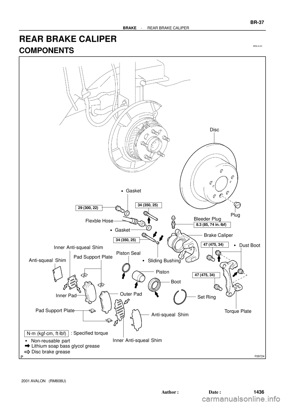
BR0LA-03
F09724
Brake Caliper
Torque Plate Piston Seal
Set Ring Piston� Dust Boot
Pad Support Plate� Sliding Bushing
Inner Pad
Anti-squeal Shim
N´m (kgf´cm, ft´lbf): Specified torque
� Non-reusable part
Lithium soap bass glycol grease
Disc brake grease
Bleeder Plug
29 (300, 22)
8.3 (85, 74 in.´lbf)
47 (475, 34)
Inner Anti-squeal Shim Anti-squeal Shim
Plug
47 (475, 34)
Boot
Pad Support Plate
Outer Pad
Inner Anti-squeal Shim
34 (350, 25)
34 (350, 25)
Flexble Hose
Disc
Gasket
�
Gasket
�
- BRAKEREAR BRAKE CALIPER
BR-37
1436 Author�: Date�:
2001 AVALON (RM808U)
REAR BRAKE CALIPER
COMPONENTS
Page 536 of 1897
BR153-01
F09726
F09727
F09728
- BRAKEREAR BRAKE CALIPER
BR-39
1438 Author�: Date�:
2001 AVALON (RM808U)
DISASSEMBLY
1. REMOVE CYLINDER BOOT SET RING AND CYL-
INDER BOOT
Using a screwdriver, remove the cylinder boot set ring and cylin-
der boot from the cylinder.
2. REMOVE PISTON
(a) Place a piece of cloth or similar, between the piston and
caliper.
(b) Use compressed air to remove the piston from the cylin-
der.
CAUTION:
Do not place your fingers in front of the piston when using
compressed air.
3. REMOVE PISTON SEAL
Using a screwdriver, remove the piston seal from the cylinder.
4. REMOVE 2 DUST BOOTS
Page 593 of 1897
B06475
No.2 Timing Belt CoverTiming Belt
Gasket
Timing Belt Guide
No.2 Generator
Bracket RH Engine Mounting Bracket
28 (290, 21)
Crankshaft
Pulley
215 (2,200, 159)
Gasket
Engine Wire Protector
125 (1,300, 94)
*88 (900, 65)
RH Camshaft Timing Pulley
43 (400, 32)
No.2 Idler Pulley
125 (1,300, 94)
Dust Boot
Timing Belt Tensioner
27 (280, 20)
� Non-reusable part
*For use with SSTNo.1 Timing Belt Cover
LH Camshaft
Timing Pulley
N´m (kgf´cm, ft´lbf) : Specified torque
CO-4
- COOLINGWATER PUMP
1197 Author�: Date�:
2001 AVALON (RM808U)
Page 1320 of 1897
A05070
Timing Belt
Gasket No.2 Timing Belt Cover
RH Engine Mounting Bracket
Crankshaft
Pulley No.1 Timing Belt Cover
Gasket
Engine Wire
Protector
No.2 Idler Pulley
RH Camshaft Timing Pulley
LH Camshaft
Timing Pulley
Timing Belt TensionerTiming Belt Guide
No.2 Generator
Bracket
Dust Boot
N´m (kgf´cm, ft´lbf) : Specified torque
* For use with SST� Non-reusable part
28 (290, 21)
215 (2,200, 159)
125 (1,300, 94)
*88 (900, 65)
27 (280, 20)
43 (440, 32)
125 (1,300, 94)
EM-28
- ENGINE MECHANICALCYLINDER HEAD
1012 Author�: Date�:
2001 AVALON (RM808U)
Page 1378 of 1897
A06659
No.2 Timing Belt CoverTiming Belt
Timing Belt Guide
No.2 Generator
Bracket RH Engine Mounting Bracket
Crankshaft
PulleyGasket
Engine Wire
Protector
RH Camshaft Timing Pulley
No.2 Idler Pulley
Crankshaft
Timing PulleyDust Boot
Timing Belt Plate Plate Washer
�
215 (2,200, 159)
43 (440, 32)
27 (280, 20)
Timing Belt Tensioner
N´m (kgf´cm, ft´lbf) : Specified torque
� Non-reusable part
28 (290, 21)
No.1 Timing Belt Cover
125 (1,300, 94)
*88 (900, 65)
LH Camshaft
Timing Pulley
No.1 Idler Pulley
34 (350, 25)
� Precoated part
* For use with SST
125 (1,300, 94)
EM-14
- ENGINE MECHANICALTIMING BELT
998 Author�: Date�:
2001 AVALON (RM808U)
Page 1383 of 1897

7. INSTALL TIMING BELT")
A02338
5th4th3rd
2nd
6th
1st
A05064
1.27 mm
Hexagon
Wrench
A05065
A05066
1.27 mm
Hexagon
Wrench
- ENGINE MECHANICALTIMING BELT
EM-23
1007 Author�: Date�:
2001 AVALON (RM808U)
7. INSTALL TIMING BELT
NOTICE:
The engine should be cold.
(a) Remove any oil or water on the pulleys, and keep them
clean.
NOTICE:
Only wipe the pulleys; do not use any cleansing agent.
(b) Face the front mark on the timing belt forward.
(c) Align the installation mark on the timing belt with the tim-
ing mark of the crankshaft timing pulley.
(d) Align the installation marks on the timing belt with the tim-
ing marks of the camshaft timing pulleys.
(e) Install the timing belt in this order:
1st: Crankshaft timing pulley
2nd: Water pump pulley
3rd: LH camshaft timing pulley
4th: No.2 idler pulley
5th: RH camshaft timing pulley
6th: No.1 idler pulley
8. SET TIMING BELT TENSIONER
(a) Using a press, slowly press in the push rod using 981 -
9,807 N (100 - 1,000 kgf, 200 - 2,205 lbf) of pressure.
(b) Align the holes of the push rod and housing, pass a 1.27
mm hexagon wrench through the holes to keep the set-
ting position of the push rod.
(c) Release the press.
(d) Install the dust boot to the tensioner.
9. INSTALL TIMING BELT TENSIONER
(a) Temporarily install the tensioner with the 2 bolts.
(b) Alternately tighten the 2 bolts.
Torque: 27 N´m (280 kgf´cm, 20 ft´lbf)
(c) Remove the 1.27 mm hexagon wrench from the tension-
er.


Crankshaft
Pulley
215 (2,200, 159)
Gasket
Engine Wire Protector
125 (1")

