Page 1784 of 1897

DISASSEMBLY
NOTICE:
When using a vise, do not")
SR0EV-05
W04228
SST
F13587
SST
R00429
Matchmarks
W04230
R11644
Claw Washer
- STEERINGPOWER STEERING GEAR
SR-41
1504 Author�: Date�:
2001 AVALON (RM808U)
DISASSEMBLY
NOTICE:
When using a vise, do not overtighten it.
1. SECURE PS GEAR ASSEMBLY IN VISE
Using SST, secure the PS gear assembly in a vise.
SST 09612-00012
2. REMOVE 2 TURN PRESSURE TUBES
(a) Using SST, remove the 2 turn pressure tubes.
SST 09023-38200
(b) Remove the 4 O-rings from the 2 turn pressure tubes.
3. REMOVE RH AND LH TIE ROD ENDS AND LOCK
NUTS
(a) Place matchmarks on the tie rod end and rack end.
(b) Loosen the lock nut, and remove the tie rod end and lock
nut.
(c) Employ the same manner described above to the other
side.
4. REMOVE RH AND LH CLIPS, RACK BOOTS AND
CLAMPS
(a) Using a screwdriver, loosen the clamp.
NOTICE:
Be careful not to damage the rack boot.
(b) Remove the clip and rack boot.
(c) Employ the same manner described above to the other
side.
HINT:
Mark the RH and LH rack boot.
5. REMOVE RH AND LH RACK ENDS AND CLAW WASH-
ERS
(a) Using a screwdriver and hammer, unstake the claw wash-
er.
NOTICE:
Avoid any impact on the steering rack.
Page 1796 of 1897

or less
SST
R00429
Matchmarks SR-54
- STEERINGPOWER STEERING GEAR
1517 Author�: Date�:
2001 AVALON (RM808U)
(c) Using a brass bar and hammer, stake the")
R11668
Brass Bar
R11669
W04223
2 mm
(0.79 in.)
or less
SST
R00429
Matchmarks SR-54
- STEERINGPOWER STEERING GEAR
1517 Author�: Date�:
2001 AVALON (RM808U)
(c) Using a brass bar and hammer, stake the claw washer.
NOTICE:
Avoid any impact on the steering rack.
(d) Employ the same manner described above to the other
side.
18. INSTALL RH AND LH RACK BOOTS, CLAMPS AND
CLIPS
(a) Ensure that the steering rack hole is not clogged with
grease.
HINT:
If the hole is clogged, the pressure inside the rack boot will
change after it is assembled and the steering wheel is turned.
(b) Install the rack boot, clip and a new clamp.
NOTICE:
Be careful not to damage or twist the rack boot.
(c) Using SST, tighten the clamp as shown in the illustration.
SST 09521-24010
(d) Employ the same manner described above to the other
side.
19. INSTALL RH AND LH TIE ROD ENDS AND LOCK NUTS
(a) Screw the lock nut and tie rod end onto the rack end until
the matchmarks are aligned.
(b) After adjusting toe-in, torque the lock nut (See page
SA-4).
Torque: 74 N´m (750 kgf´cm, 54 ft´lbf)
(c) Employ the same manner described above to the other
side.
Page 1838 of 1897
W03094
SST
F02207
SA-10
- SUSPENSION AND AXLEFRONT AXLE HUB
1344 Author�: Date�:
2001 AVALON (RM808U)
6. DISCONNECT TIE ROD END FROM STEERING
KNUCKLE
(a) Remove the cotter pin and nut.
Torque: 49 N´m (500 kgf´cm, 36 ft´lbf)
(b) Using SST, disconnect the tie rod end from the steering
knuckle.
SST 09610-20012
7. DISCONNECT LOWER BALL JOINT FROM LOWER
SUSPENSION ARM
Remove the 2 nuts and bolt.
Torque: 127 N´m (1,300 kgf´cm, 94 ft´lbf)
8. REMOVE STEERING KNUCKLE WITH AXLE HUB
(a) Remove the 2 nuts and bolts on the lower side of the
shock absorber.
(b) Remove the steering knuckle with the axle hub.
NOTICE:
Be careful not to damage the boot and ABS speed sensor
rotor.
Page 1839 of 1897
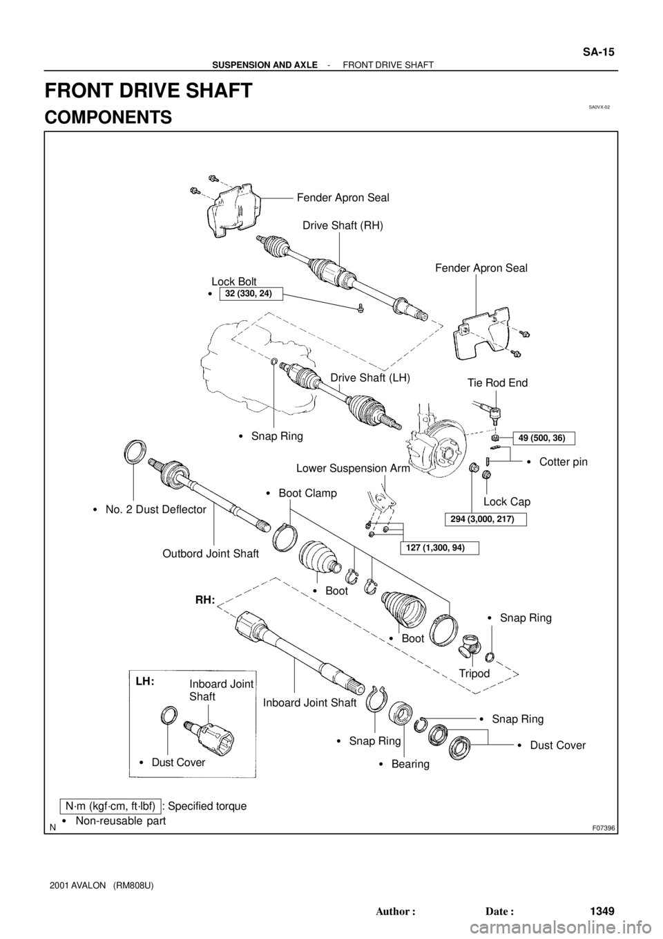
SA0VX-02
F07396
Fender Apron Seal
Drive Shaft (RH)
32 (330, 24)�Lock Bolt
� Snap Ring
� No. 2 Dust Deflector
Outbord Joint Shaft
Fender Apron Seal
Tie Rod End
49 (500, 36)
� Cotter pin
Lock Cap
294 (3,000, 217)
Lower Suspension Arm
127 (1,300, 94)
� Boot Clamp
� Boot
� Boot
� Snap Ring
Tripod RH:
Inboard Joint Shaft
� Snap Ring
� Bearing
� Snap Ring
� Dust Cover LH:
Inboard Joint
Shaft
� Dust Cover
N´m (kgf´cm, ft´lbf) : Specified torque
� Non-reusable part
Drive Shaft (LH)
- SUSPENSION AND AXLEFRONT DRIVE SHAFT
SA-15
1349 Author�: Date�:
2001 AVALON (RM808U)
FRONT DRIVE SHAFT
COMPONENTS
Page 1840 of 1897

DISASSEMBLY
1. CHECK DRIVE SHAFT
(a) Check to see th")
SA1EA-03
N00191
F07391
F07392
Matchmarks
N00194
Matchmarks SA-18
- SUSPENSION AND AXLEFRONT DRIVE SHAFT
1352 Author�: Date�:
2001 AVALON (RM808U)
DISASSEMBLY
1. CHECK DRIVE SHAFT
(a) Check to see that there is no remarkable play in the out-
board joint.
(b) Check to see that the inboard joint slides smoothly in the
thrust direction.
(c) Check to see that there is no remarkable play in the radial
direction of the inboard joint.
(d) Check the boots for damage.
2. REMOVE INBOARD AND OUTBOARD JOINT BOOT
CLAMPS
(a) Using pliers, pinch the claws to compress the large in-
board joint boot clamp and remove it.
(b) Using a side cutter, cut the small inboard joint boot clamp
and remove it.
(c) Using a side cutter, cut the 2 outboard joint boot clamps
and remove them.
3. REMOVE INBOARD JOINT SHAFT
(a) Place matchmarks on the tripod, inboard and outboard
joint shafts.
NOTICE:
Do not punch the marks.
(b) Remove the inboard joint shaft from the outboard joint
shaft.
4. REMOVE TRIPOD
(a) Using a snap ring expander, remove the snap ring.
(b) Place matchmarks on the outboard joint shaft and tripod.
NOTICE:
Do not punch the marks.
(c) Using a brass bar and hammer, remove the tripod from
the outboard joint shaft.
NOTICE:
Do not tap the roller.
Page 1841 of 1897
F07394
SST
SA1446
R09717
SST
F07393
SST
- SUSPENSION AND AXLEFRONT DRIVE SHAFT
SA-19
1353 Author�: Date�:
2001 AVALON (RM808U)
5. REMOVE INBOARD AND OUTBOARD JOINT BOOTS
Slide out the 2 boots.
NOTICE:
Do not disassemble the outboard joint.
6. LH drive shaft:
REMOVE DUST COVER
Using SST and a press, remove the dust cover from the inboard
joint shaft.
SST 09950-00020
7. RH drive shaft:
DISASSEMBLE INBOARD JOINT SHAFT
(a) Using a press, remove the transaxle side dust cover from
the inboard joint shaft.
(b) Using SST and a press, remove the bearing side dust
cover.
SST 09950-00020
(c) Using a snap ring expander, remove the snap ring.
(d) Using SST and a press, remove the bearing.
SST 09950-00020
(e) Remove the snap ring.
Page 1845 of 1897

4. TEMPORARILY INSTALL OUTBOARD AND INBOARD
JOIN")
F01747
Inboard Joint BootOutboard Joint Boot
Vinyl tape
R00764
SA-22
- SUSPENSION AND AXLEFRONT DRIVE SHAFT
1356 Author�: Date�:
2001 AVALON (RM808U)
4. TEMPORARILY INSTALL OUTBOARD AND INBOARD
JOINT BOOTS AND NEW BOOT CLAMPS
HINT:
�Before installing the boots, wrap the spline of the out-
board joint shaft with vinyl tape to prevent the boots from
being damaged.
�Before installing the boots, place 3 new clamps to the
small boot ends and large boot end (outboard joint side).
5. INSTALL TRIPOD
(a) Place the beveled side of the tripod axial spline toward the
outboard joint.
(b) Align the matchmarks placed before removal.
(c) Using a brass bar and hammer, tap in the tripod to the out-
board joint shaft.
NOTICE:
Do not tap the roller.
(d) Using a snap ring expander, install a new snap ring.
6. INSTALL BOOT TO OUTBOARD JOINT
Before assembling the boot, pack the outboard joint and boot
with grease in the boot kit.
Grease capacity (Color = Gray):
105 - 125 g (3.7 - 4.4 oz.)
7. INSTALL INBOARD JOINT SHAFT TO OUTBOARD
JOINT SHAFT
(a) Pack the inboard joint and boot with grease in the boot kit.
Grease capacity (Color = Yellow ocher):
170 - 190 g (6.0 - 6.7 oz.)
(b) Align the matchmarks placed before removal, and install
the inboard joint shaft to the outboard joint shaft.
(c) Temporarily install the boot to the inboard joint shaft.
8. CHECK DRIVE SHAFT LENGTH
(a) Make sure that the 2 boots are on the shaft groove.
(b) Make sure that the 2 boots are not stretched or contracted
when the drive shaft is at standard length.
Drive shaft standard length:
LH586.0 ± 2.0 mm (23.071 ± 0.079 in.)
RH881.6 ± 2.0 mm (34.709 ± 0.079 in.)
Page 1846 of 1897
F07391
R10353
SST
F00616
Clearance
SST
ABC
- SUSPENSION AND AXLEFRONT DRIVE SHAFT
SA-23
1357 Author�: Date�:
2001 AVALON (RM808U)
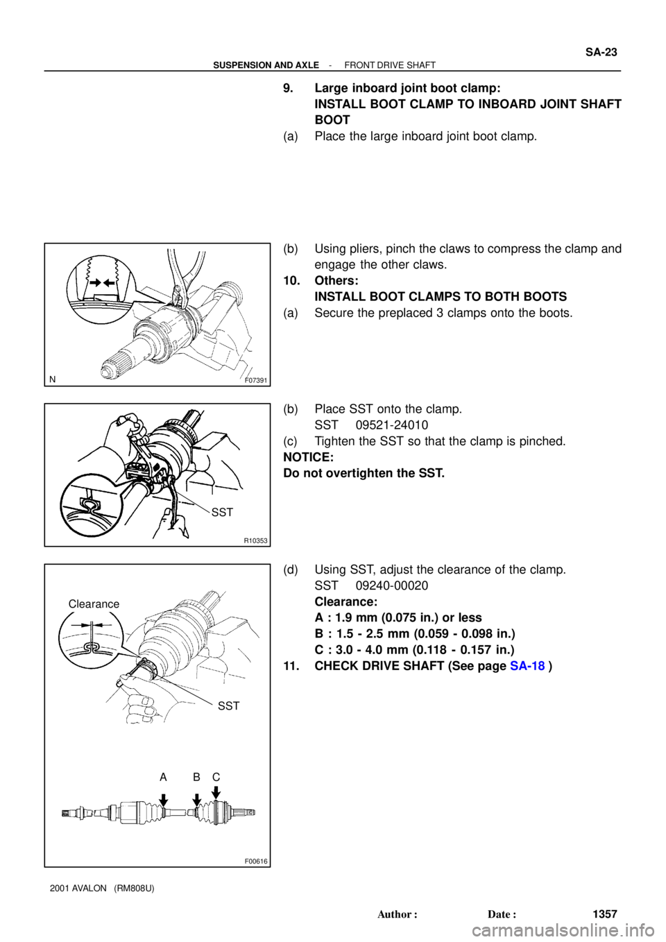
9. Large inboard joint boot clamp:
INSTALL BOOT CLAMP TO INBOARD JOINT SHAFT
BOOT
(a) Place the large inboard joint boot clamp.
(b) Using pliers, pinch the claws to compress the clamp and
engage the other claws.
10. Others:
INSTALL BOOT CLAMPS TO BOTH BOOTS
(a) Secure the preplaced 3 clamps onto the boots.
(b) Place SST onto the clamp.
SST 09521-24010
(c) Tighten the SST so that the clamp is pinched.
NOTICE:
Do not overtighten the SST.
(d) Using SST, adjust the clearance of the clamp.
SST 09240-00020
Clearance:
A : 1.9 mm (0.075 in.) or less
B : 1.5 - 2.5 mm (0.059 - 0.098 in.)
C : 3.0 - 4.0 mm (0.118 - 0.157 in.)
11. CHECK DRIVE SHAFT (See page SA-18)