SA0VY-02
FA1535
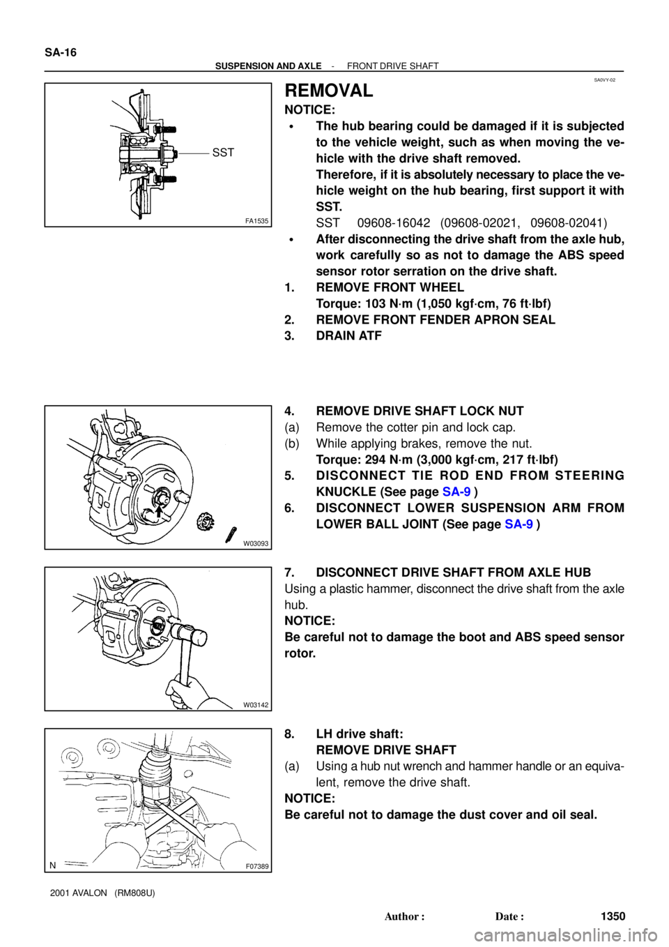
SST
W03093
W03142
F07389
SA-16
- SUSPENSION AND AXLEFRONT DRIVE SHAFT
1350 Author�: Date�:
2001 AVALON (RM808U)
REMOVAL
NOTICE:
�The hub bearing could be damaged if it is subjected
to the vehicle weight, such as when moving the ve-
hicle with the drive shaft removed.
Therefore, if it is absolutely necessary to place the ve-
hicle weight on the hub bearing, first support it with
SST.
SST 09608-16042 (09608-02021, 09608-02041)
�After disconnecting the drive shaft from the axle hub,
work carefully so as not to damage the ABS speed
sensor rotor serration on the drive shaft.
1. REMOVE FRONT WHEEL
Torque: 103 N´m (1,050 kgf´cm, 76 ft´lbf)
2. REMOVE FRONT FENDER APRON SEAL
3. DRAIN ATF
4. REMOVE DRIVE SHAFT LOCK NUT
(a) Remove the cotter pin and lock cap.
(b) While applying brakes, remove the nut.
Torque: 294 N´m (3,000 kgf´cm, 217 ft´lbf)
5. DISCONNECT TIE ROD END FROM STEERING
KNUCKLE (See page SA-9)
6. DISCONNECT LOWER SUSPENSION ARM FROM
LOWER BALL JOINT (See page SA-9)
7. DISCONNECT DRIVE SHAFT FROM AXLE HUB
Using a plastic hammer, disconnect the drive shaft from the axle
hub.
NOTICE:
Be careful not to damage the boot and ABS speed sensor
rotor.
8. LH drive shaft:
REMOVE DRIVE SHAFT
(a) Using a hub nut wrench and hammer handle or an equiva-
lent, remove the drive shaft.
NOTICE:
Be careful not to damage the dust cover and oil seal.
SA3213
Front A
DB
C
F02245
F02246
SA0028
Front AB
A B
A: Inside
B: Outside SA-6
- SUSPENSION AND AXLEFRONT WHEEL ALIGNMENT
1340 Author�: Date�:
2001 AVALON (RM808U)
5. INSPECT TOE-IN
Toe-in:
Toe-in
(total)A + B: 0° ± 12' (0° ± 0.2°)
C - D: 0 ± 2 mm (0 ± 0.08 in.)
If the toe-in is not within the specified value, adjust it at the rack
ends.
6. ADJUST TOE-IN
(a) Remove the rack boot set clips.
(b) Loosen the tie rod end lock nuts.
(c) Turn the right and left rack ends by an equal amount to
adjust the toe-in.
HINT:
Try to adjust the toe-in to the center of the specified value.
(d) Make sure that the lengths of the right and left rack ends
are the same.
Rack end length difference: 1.5 mm (0.059 in.) or less
(e) Torque the tie rod end lock nuts.
Torque: 74 N´m (750 kgf´cm, 54 ft´lbf)
(f) Place the boots on the seats and install the clips.
HINT:
Make sure that the boots are not twisted.
7. INSPECT WHEEL ANGLE
Turn the steering wheel fully, and measure the turning angle.
Wheel turning angle:
Inside wheel35°45' ± 1° (35.75° ± 1°)
Outside wheel: Reference31°23' (31.38°)
If the right and left inside wheel angles differ from the specified
value, check the right and left rack end lengths.