Page 1012 of 1897
- DIAGNOSTICSENGINE
DI-133
289 Author�: Date�:
2001 AVALON (RM808U)
CHECK:
Check whether or not DTC P1349/P1354 is stored (See page DI-3).
OK:
DTC P1349/P1354 is not stored.
OK VVT system is OK.*
*: DTCs P1349 and P1354 are also output after the foreign ob-
ject is caught in some part of the system in the engine oil and
the system returns to normal in a short time. As ECM controls
so that foreign objects are ejected, there is no problem about
VVT. There is also no problem since the oil filter should get the
foreign object in the engine oil.
NG
Replace ECM.
Page 1043 of 1897
P00495
Outside
Inside
- DIAGNOSTICSENGINE
DI-9
165 Author�: Date�:
2001 AVALON (RM808U)
NO Proceed to page ST-18, and continue to trouble-
shoot.
YES
3 Does engine start?
NO Go to step 7.
YES
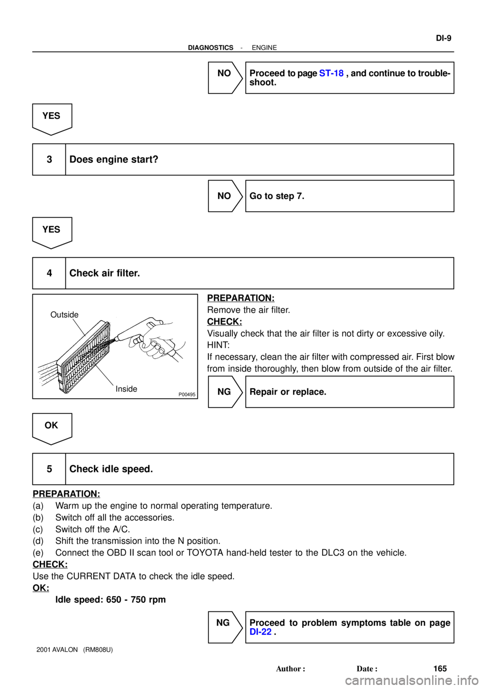
4 Check air filter.
PREPARATION:
Remove the air filter.
CHECK:
Visually check that the air filter is not dirty or excessive oily.
HINT:
If necessary, clean the air filter with compressed air. First blow
from inside thoroughly, then blow from outside of the air filter.
NG Repair or replace.
OK
5 Check idle speed.
PREPARATION:
(a) Warm up the engine to normal operating temperature.
(b) Switch off all the accessories.
(c) Switch off the A/C.
(d) Shift the transmission into the N position.
(e) Connect the OBD II scan tool or TOYOTA hand-held tester to the DLC3 on the vehicle.
CHECK:
Use the CURRENT DATA to check the idle speed.
OK:
Idle speed: 650 - 750 rpm
NG Proceed to problem symptoms table on page
DI-22.
Page 1289 of 1897

No.2 Idler Pulley Bracket
Water Seal Plate
Engine Coolant
Drain Union
Oil Filter")
EM04B-04
A10521
Knock Sensor Connector
Engine Wire Band
Engine WireKnock Sensor
Water Inlet Housing
(With Water Inlet)
No.2 Idler Pulley Bracket
Water Seal Plate
Engine Coolant
Drain Union
Oil Filter Union
Oil Filter � Gasket
Cylinder Block
Side Cover
� Gasket
Water Pump
� Crankshaft
Front Oil Seal
Crankshaft
Position Sensor
Connector� Oil Pressure
Switch
Oil Pressure Switch
Connector
A/C Compressor
Housing Bracket
No.1 Oil Pan
x 17 Oil Pump
� Gasket
� Gasket
Engine WireGenerator
Drain Plugx 10No.2 Oil Pan Oil Strainer
� Non-reusable part
N´m (kgf´cm, ft´lbf): Specified torque
Precoated part �
8 (80, 69 in.´lbf)
8 (80, 69 in.´lbf)
10 mm Head 8 (80, 69 in.´lbf)
12 mm Head 19.5 (200, 14)
10 mm Head 8 (80, 69 in.´lbf)
12 mm Head 19.5 (200, 14)
45 (460, 33)
8 (80, 69 in.´lbf)
9 (90, 78 in.´lbf)
x 8
8 (80, 69 in.´lbf)
28 (290, 21)
�
18 (180, 13)
25 (250, 18)
39 (400, 29)
No.2 ECT Switch
Connector
� O-Ring
x 9
19.5 (200, 14)
- ENGINE MECHANICALCYLINDER BLOCK
EM-81
1065 Author�: Date�:
2001 AVALON (RM808U)
CYLINDER BLOCK
COMPONENTS
Page 1292 of 1897

13.")
P12389
SST
A05253
P18763
WaterSeal
Plate
Oil Filter
Union
12 mm
Hexagon
Wrench
Coolant
Drain
Union
A02010
P12508
EM-84
- ENGINE MECHANICALCYLINDER BLOCK
1068 Author�: Date�:
2001 AVALON (RM808U)
13. REMOVE KNOCK SENSORS
(a) Disconnect the 2 knock sensor connectors.
(b) Using SST, remove the 2 knock sensors.
SST 09816-30010
14. REMOVE WATER INLET HOUSING
(a) Remove the engine wire band.
(b) Disconnect the engine wire clamp from the bracket.
(c) Remove the 8 bolts, 2 nuts and water inlet housing.
15. REMOVE WATER PUMP (See page CO-6)
16. REMOVE NO.2 OIL PAN (See page LU-9)
17. REMOVE OIL STRAINER (See page LU-3)
18. REMOVE NO.1 OIL PAN (See page LU-3)
19. REMOVE OIL PUMP (See page LU-9)
20. REMOVE OIL FILTER (See page LU-3)
21. REMOVE OIL FILTER UNION
Using a 12 mm hexagon wrench, remove the oil filter union.
22. REMOVE WATER SEAL PLATE
Remove the 2 nuts and seal plate.
23. REMOVE ENGINE COOLANT DRAIN UNION
24. REMOVE CYLINDER BLOCK SIDE COVER
Remove the 3 bolts, 2 nuts, cylinder block side cover and gas-
ket.
25. REMOVE REAR OIL SEAL RETAINER
(a) Remove the 6 bolts.
(b) Using a screwdriver, remove the oil seal retainer by prying
the portions between the oil seal retainer and main bear-
ing cap.
Page 1313 of 1897

17. INSTALL ENGINE COOLANT DRAIN UNION
(a) Apply seal packin")
P12477
Seal Packing
Z09223
Seal Width
3 - 5 mmA
BA
B
- ENGINE MECHANICALCYLINDER BLOCK
EM-107
1091 Author�: Date�:
2001 AVALON (RM808U)
17. INSTALL ENGINE COOLANT DRAIN UNION
(a) Apply seal packing to 2 or 3 threads.
Seal packing: Part No. 08826-00100 or equivalent
(b) Install the drain union.
Torque: 39 N´m (400 kgf´cm, 29 ft´lbf)
HINT:
After applying the specified torque, rotate the drain union clock-
wise until its drain port is facing downward.
18. INSTALL WATER SEAL PLATE
(a) Remove any old packing (FIPG) material and be careful
not to drop any oil on the contact surfaces of the seal plate
and cylinder block.
�Using a razor blade and gasket scraper, remove all
the old packing (FIPG) material from the gasket sur-
faces and sealing groove.
�Thoroughly clean all components to remove all the
loose material.
�Using a non-residue solvent, clean both sealing
surfaces.
(b) Apply seal packing to the seal plate as shown in the il-
lustration.
Seal packing: Part No. 08826-00100 or equivalent
�Install a nozzle that has been cut to a 3 - 5 mm (0.12
- 0.20 in.) opening.
�Parts must be assembled within 3 minutes of ap-
plication. Otherwise the material must be removed
and reapplied.
�Immediately remove nozzle from the tube and rein-
stall cap.
(c) Install the seal plate with the 2 nuts.
Torque: 18 N´m (180 kgf´cm, 13 ft´lbf)
19. INSTALL OIL FILTER UNION
Torque: 30 N´m (310 kgf´cm, 22 ft´lbf)
20. INSTALL OIL FILTER (See page LU-3)
21. INSTALL OIL PUMP (See page LU-15)
22. INSTALL NO.1 OIL PAN (See page LU-15)
23. INSTALL OIL STRAINER (See page LU-15)
24. INSTALL NO.2 OIL PAN (See page LU-15)
25. INSTALL WATER PUMP (See page CO-8)
26. INSTALL WATER INLET HOUSING
(a) Remove any old packing (FIPG) material and be careful
not to drop any oil on the contact surfaces of the water in-
let housing and cylinder block.
�Using a razor blade and gasket scraper, remove all
the old packing (FIPG) material from the gasket sur-
faces and sealing grooves.
�Thoroughly clean all components to remove all the
loose material.
Page 1322 of 1897

A05703
Adjusting Shim
Valve Lifter
Keeper
Spring Retainer
Valve Spring
Spring Seat
� Oil Seal
Valve � Valve Guide BushingLH Cylinder Head Cover
LH Intake
Camshaft
Snap Ring Camshaft Sub-Gear
LH Exhaust
Camshaft RH Cylinder Head Cover
Gasket
RH Intake
Camshaft Camshaft Sub-Gear
Camshaft Gear Spring
RH Exhaust
CamshaftWave Washer
Semi-Circular PlugSemi-Circular
Plug
LH Cylinder Head
Camshaft
Bearing Cap
� Camshaft Oil Seal RH Cylinder Head
� RH Cylinder
Head Gasket
� LH Cylinder Head Gasket18 (185, 13)x 8
16 (160, 12)
See Page EM-59
1st 54 (550, 40)
2nd Turn 90°
N´m (kgf´cm, ft´lbf) : Specified torque
� Non-reusable part
� Spark Plug
Tube Gasket
Wave WasherGasketSnap RingCamshaft Gear Spring
Oil Control Valve Filter
� Gasket
Camshaft Timing
Gear (VVT-i)
� Gasket
� Gasket
Oil Control
Valve FilterCylinder Head
Rear CoverCylinder Head
Rear Cover� Gasket
150 (1,530, 110)
NOTICE:
Intake Camshaft
Do not remove or install the camshaft timing
gear (VVT-i) beside changing VVT-i or the
camshaft.
�
EM-30
- ENGINE MECHANICALCYLINDER HEAD
1014 Author�: Date�:
2001 AVALON (RM808U)
Page 1324 of 1897
A05275
- ENGINE MECHANICALCYLINDER HEAD
EM-41
1025 Author�: Date�:
2001 AVALON (RM808U)
4. REMOVE OIL CONTROL VALVE FILTER
Remove the plug, gasket and valve filter.
Page 1346 of 1897
Adhesive
P12572
Protrusion
P12869
Flush
A05418
EM-56
- ENGINE MECHANICALCYLINDER HEAD
1040 Author�: Date�:
2001 AVALON (RM808U)
REASSEMBLY
HINT:
�Thoroughl")
EM0ZI-02
P1151110 - 15 mm (0.39 - 0.59 in.)Adhesive
P12572
Protrusion
P12869
Flush
A05418
EM-56
- ENGINE MECHANICALCYLINDER HEAD
1040 Author�: Date�:
2001 AVALON (RM808U)
REASSEMBLY
HINT:
�Thoroughly clean all parts to be assembled.
�Before installing the parts, apply new engine oil to all slid-
ing and rotating surfaces.
�Replace all gaskets and oil seals with new ones.
1. INSTALL SPARK PLUG TUBES
HINT:
When using a new cylinder head, spark plug tubes must be
installed.
(a) Apply adhesive to the end of the spark plug tube.
Adhesive: Part No. 08833-00070, THREE BOND 1324
or equivalent
(b) Using a press, press in a new spark plug tube until there
is 42.4 - 43.4 mm (1.669 - 1.709 in.) protruding from the
camshaft bearing cap installation surface of the cylinder
head.
NOTICE:
Avoid pressing a new spark plug tube in too far by measur-
ing the amount of the protrusion while pressing.
2. INSTALL PCV PIPES
HINT:
When using a new cylinder head, PCV pipe must be installed.
Using a wooden block and hammer, tap in a new PCV pipe until
its top side is flush with the cylinder head edge.
NOTICE:
Be careful not to damage the cylinder head edge.
3. INSTALL OIL CONTROL VALVE FILTER
(a) Assemble the valve filter and plug.
(b) Install the plug with new gasket.
Torque: 45 N´m (460 kgf´cm, 33 ft´lbf)