Page 97 of 1897
AT3412
AX03Z-05
AX-42
- AUTOMATIC TRANSAXLEAUTOMATIC TRANSAXLE UNIT
1332 Author�: Date�:
2001 AVALON (RM808U)
INSTALLATION
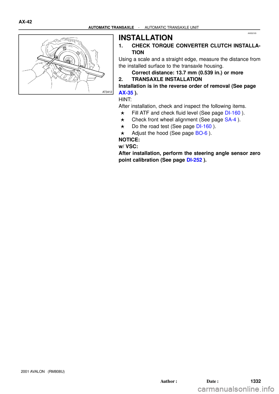
1. CHECK TORQUE CONVERTER CLUTCH INSTALLA-
TION
Using a scale and a straight edge, measure the distance from
the installed surface to the transaxle housing.
Correct distance: 13.7 mm (0.539 in.) or more
2. TRANSAXLE INSTALLATION
Installation is in the reverse order of removal (See page
AX-35).
HINT:
After installation, check and inspect the following items.
�Fill ATF and check fluid level (See page DI-160).
�Check front wheel alignment (See page SA-4).
�Do the road test (See page DI-160).
�Adjust the hood (See page BO-6).
NOTICE:
w/ VSC:
After installation, perform the steering angle sensor zero
point calibration (See page DI-252).
Page 728 of 1897

(b) In case of using TOYOTA hand")
F07887
TOYOTA Hand-
held Tester
DLC3
F19119
DLC1
Ts E1
DLC3
CG
Ts
DI-256
- DIAGNOSTICSABS WITH EBD & BA & TRAC & VSC SYSTEM
412 Author�: Date�:
2001 AVALON (RM808U)
(b) In case of using TOYOTA hand-held tester:
Check the sensor signal.
(1) Hook up the TOYOTA hand- held tester to the
DLC3.
(2) Do step (3) - (6) on the previous page.
(3) Read the DTC by following the prompts on the tes-
ter screen.
HINT:
Please refer to the TOYOTA hand-held tester operator's manu-
al for further details.
DTC of speed sensor check function:
Code No.DiagnosisTrouble Area
C1271 / 71Low output voltage of right front speed sensor
�Right front speed sensor
�Sensor installation
�Right front speed sensor rotor
C1272 / 72Low output voltage of left front speed sensor
�Left front speed sensor
�Sensor installation
�Left front speed sensor rotor
C1273 / 73Low output voltage of right rear speed sensor
�Right rear speed sensor
�Sensor installation
�Right rear speed sensor rotor
C1274 / 74Low output voltage of left rear speed sensor
�Left rear speed sensor
�Sensor installation
�Left rear speed sensor rotor
C1275 / 75Abnormal change in output signal of right front speed sen-
sorRight front speed sensor rotor
C1276 / 76Abnormal change in output signal of left front speed sensorLeft front speed sensor rotor
C1277 / 77Abnormal change in output signal of right rear speed sensorRight rear speed sensor rotor
C1278 / 78Abnormal change in output signal of left rear speed sensorLeft rear speed sensor rotor
3. STEERING ANGLE SENSOR ZERO POINT CALIBRA-
TION
NOTICE:
Make sure to perform steering angle sensor zero point cal-
ibration when:
�Replacing the steering angle sensor or ECU.
�Adjusting the front wheel alignment of the steering
wheel center point in accordance with removal and
installation or replacement of the suspension, axle or
steering parts.
(a) Using the SST, connect terminals Ts and E
1 of DLC1 or
Ts and CG of DLC3
.
SST DLC1: 09843-18020
DLC3: 09843-18040
(b) Turn the ignition switch to the ON position, without start-
ing the engine.
(c) Make sure the steering wheel off center angle is within 3
degrees of center before attempting calibration.
Page 1414 of 1897

5. FOR VEHICLES EQUIPPED WITH TRACTION CON-
TROL (TRAC) & VEHICLE SKID CONTROL (VSC) SYS-
TEM
NOT")
B09711
B09808
B09711
IN-18
- INTRODUCTIONFOR ALL OF VEHICLES
18 Author�: Date�:
2001 AVALON (RM808U)
5. FOR VEHICLES EQUIPPED WITH TRACTION CON-
TROL (TRAC) & VEHICLE SKID CONTROL (VSC) SYS-
TEM
NOTICE:
�When replacing the steering angle sensor or ECU, or
when adjusting the front wheel alignment or steering
wheel center point in accordance with the removing
and installing or replacing the suspension, axle, or
steering parts, make sure to perform the steering
angle sensor zero point calibration (See page
DI-252).
�Do not remove or install the VSC related parts unless
necessary. Otherwise, there is a possibility that the
setting of the VSC to be affected.
�When working on the VSC related operation, make
sure to check that the preparations before and after
work are completed according to the following
instruction.
�When using a drum tester such as a speedometer tes-
ter or chassis dynamometer, etc., or jacking up the
front wheels and driving the wheels, always push in
the TRAC & VSC cut (ºVSC OFFº) switch and turn the
TRAC & VSC system OFF.
(a) Press the VSC OFF switch.
(b) Check that the VSC OFF indicator light comes ON.
HINT:
The VSC OFF indicator light should be always OFF when the
engine is restarted.
(c) Begin measurements.
(d) Press the VSC OFF switch again to change the TRAC &
VSC system to operational condition and check that the
VSC OFF indicator light goes off.
HINT:
�The SLIP indicator light blinks when the TRAC system is
operational.
�The SLIP indicator light blinks and the VSC buzzer
sounds when the VSC system is operational.
Page 1576 of 1897

SUSPENSION AND AXLE
SERVICE DATA
Cold tire inflation
pressureP205/65R15 92H Front, rear
P205/60R16")
SS04W-07
- SERVICE SPECIFICATIONSSUSPENSION AND AXLE
SS-27
143 Author�: Date�:
2001 AVALON (RM808U)
SUSPENSION AND AXLE
SERVICE DATA
Cold tire inflation
pressureP205/65R15 92H Front, rear
P205/60R16 91H Front, rear210 kPa (2.1 kgf/cm2, 31 psi)
220 kPa (2.2 kgf/cm2, 32 psi)
Vehicle heightFront*1
Rear*2213 mm (8.39 in.)
266 mm (10.47 in.)
Camber
Right-left error-0°37' ± 45' (-0.62° ± 0.75°)
45' (0.75°) or less
Front Wheel
Caster
Right-left error2°10' ± 45' (2.17° ± 0.75°)
45' (0.75°) or less
Front Wheel
alignmentSteering axis inclination
Right-left error13°04' ± 45' (13.07° ± 0.75°)
45' (0.75°) or less
Toe-in (total)
Rack end length difference0° ± 12' (0° ± 0.2°, 0 ± 2 mm, 0 ± 0.08 in.)
1.5 mm (0.059 in.) or less
Wheel angle Inside wheel
Outside wheel: Reference35°45' ± 1° (35.75° ± 1°)
31°23' (31.38°)
Rear wheel
Camber
Right-left error-0°43' ± 45' (-0.72° ± 0.75°)
45' (0.75°) or less
Rear wheel
alignmentToe-in (total)
No. 2 lower suspension arm length difference0°24' ± 12' (0.4° ± 0.2°, 4 ± 2 mm, 0.16 ± 0.08 in.)
1 mm (0.04 in.) or less
FtlAxle bearing backlash Maximum0.05 mm (0.0020 in.)Front axleAxle hub deviationMaximum0.05 mm (0.0020 in.)
Front drive shaftDrive shaft standard length LH
RH586.0 ± 2.0 mm (23.071 ± 0.079 in.)
881.6 ± 2.0 mm (34.709 ± 0.079 in.)
Ft iLower ball joint turning torque1.0 - 3.4 N´m (10 - 35 kgf´cm, 8.7 - 30 in.´lbf)Front suspensionStabilizer bar link ball joint turning torque0.05 - 1.0 N´m (0.5 - 10 kgf´cm, 0.4 - 8.7 in.´lbf)
RlAxle bearing backlash Maximum0.05 mm (0.0020 in.)Rear axleAxle hub deviationMaximum0.07 mm (0.0028 in.)
RiNo. 2 lower suspension arm length512.3 mm (20.169 in.)Rear suspensionStabilizer bar link ball joint turning torque0.05 - 1.0 N´m (0.5 - 10 kgf´cm, 0.4 - 8.7 in.´lbf)
*1: Front measuring point
Measure the distance from the ground to the center of the front side lower suspension arm mounting bolt.
*2: Rear measuring point
Measure the distance from the ground to the center of the front side strut rod mounting bolt.
Page 1790 of 1897
- STEERINGPOWER STEERING GEAR
SR-57
1520 Author�: Date�:
2001 AVALON (RM808U)
12. CHECK STEERING WHEEL CENTER POINT
13. TORQUE STEERING WHEEL SET NUT
Torque: 50 N´m (510 kgf´cm, 37 ft´lbf)
14. INSTALL STEERING WHEEL PAD (See page SR-22)
15. CHECK FRONT WHEEL ALIGNMENT
(See page SA-4)
16. w/ VSC:
PERFORM STEERING ANGLE SENSOR ZERO POINT
CALIBRATION (See page DI-252)
Page 1816 of 1897

TROUBLESHOOTING
PROBLEM SYMPTOMS TABLE
Use the table below to help you find the cause of the problem. The numbers in")
SR0EC-02
SR-2
- STEERINGTROUBLESHOOTING
1465 Author�: Date�:
2001 AVALON (RM808U)
TROUBLESHOOTING
PROBLEM SYMPTOMS TABLE
Use the table below to help you find the cause of the problem. The numbers indicate the priority of the likely
cause of the problem. Check each part in order. If necessary, repair or replace these parts.
SymptomSuspect AreaSee page
Hard steering
1. Tires (Improperly inflated)
2. Power steering fluid level (Low)
3. Drive belt (Loose)
4. Front wheel alignment (Incorrect)
5. Steering system joints (Worn)
6. Suspension arm ball joints (Worn)
7. Steering column (Binding)
8. Power steering vane pump
9. Power steering gearSA-2
SR-5
SR-3
SA-4
-
SA-38
-
SR-25
SR-37
Poor return
1. Tires (Improperly inflated)
2. Front wheel alignment (Incorrect)
3. Steering column (Binding)
4. Power steering gearSA-2
SA-4
-
SR-37
Excessive play
1. Steering system joints (Worn)
2. Suspension arm ball joints (Worn)
3. Universal joint, Intermediate shaft, Sliding yoke (Worn)
4. Front wheel bearing (Worn)
5. Power steering gear-
SA-38
-
SA-9
SR-37
Abnormal noise
1. Power steering fluid level (Low)
2. Steering system joints (Worn)
3. Power steering vane pump
4. Power steering gearSR-5
-
SR-25
SR-37
Page 1851 of 1897
SA0VD-03
R08850
R08861SSTSST
- SUSPENSION AND AXLEFRONT LOWER BALL JOINT
SA-39
1373 Author�: Date�:
2001 AVALON (RM808U)
INSTALLATION
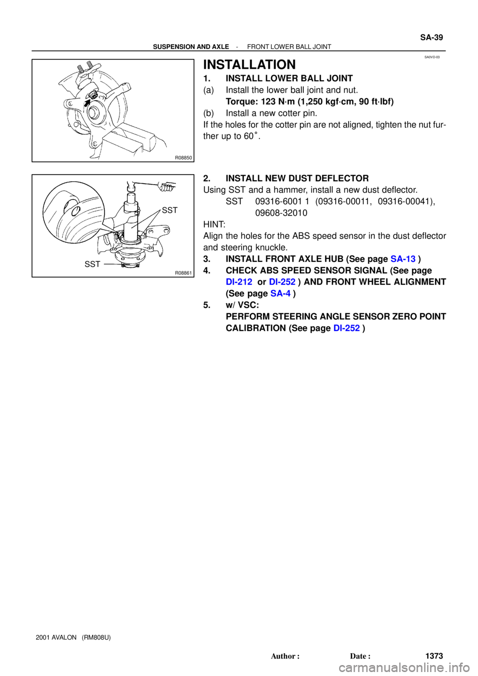
1. INSTALL LOWER BALL JOINT
(a) Install the lower ball joint and nut.
Torque: 123 N´m (1,250 kgf´cm, 90 ft´lbf)
(b) Install a new cotter pin.
If the holes for the cotter pin are not aligned, tighten the nut fur-
ther up to 60°.
2. INSTALL NEW DUST DEFLECTOR
Using SST and a hammer, install a new dust deflector.
SST 09316-6001 1 (09316-00011, 09316-00041),
09608-32010
HINT:
Align the holes for the ABS speed sensor in the dust deflector
and steering knuckle.
3. INSTALL FRONT AXLE HUB (See page SA-13)
4. CHECK ABS SPEED SENSOR SIGNAL (See page
DI-212 or DI-252) AND FRONT WHEEL ALIGNMENT
(See page SA-4)
5. w/ VSC:
PERFORM STEERING ANGLE SENSOR ZERO POINT
CALIBRATION (See page DI-252)
Page 1854 of 1897
SA0V9-02
- SUSPENSION AND AXLEFRONT LOWER SUSPENSION ARM
SA-35
1369 Author�: Date�:
2001 AVALON (RM808U)
INSTALLATION
Installation is in the reverse order of removal (See page SA-33).
HINT:
After installation, check the front wheel alignment (See page SA-4).