Page 22 of 1897
AC2FY-01
I12951
N´m (kgf´cm, ft´lbf): Specified torque
� Non-reusable part
Instrument Panel
Reinforcement
Brace
A/C Unit
Rear Heater Duct
Piping Clamp
� O-RingSuction Tube
Liquid Tube
Piping Clamp
Blower Unit
No. 3 Heater to Register Duct
DuctBrace
� O-Ring
AC-26
- AIR CONDITIONINGAIR CONDITIONING UNIT
1948 Author�: Date�:
2001 AVALON (RM808U)
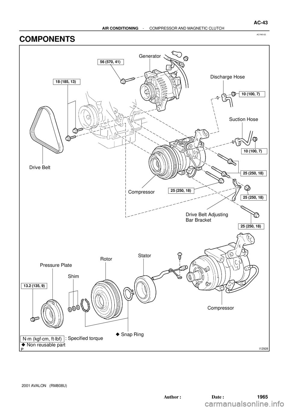
COMPONENTS
Page 23 of 1897
I12952
Air DuctHeater Radiator
Unit Case LH
Evaporator
Unit Case RHExpansion Valve
Liquid and
Suction Tube
Air Outlet Servomotor
Air Vent Duct
Auto A/C:
Aspirator HoseDrain Hose
Evaporator Temp.
Sensor
5.4 (55, 48 in.´lbf)
N´m (kgf´cm, ft´lbf) : Specified torque
� Non-reusable part
x 10
� O-Rings
AspiratorAuto A/C:
Air Mix Servomotor
(Passenger side)
� O-Rings
Auto A/C
Air Mix Servomotor
(Driver side)
Air Duct
Plate
- AIR CONDITIONINGAIR CONDITIONING UNIT
AC-27
1949 Author�: Date�:
2001 AVALON (RM808U)
Page 24 of 1897

DISASSEMBLY
1. REMOVE AIR VENT DUCT
2. REMOVE EVAPORATOR TEMP. SENSOR
Pull out the sens")
AC2HX-01
I14049
I14050
AC-30
- AIR CONDITIONINGAIR CONDITIONING UNIT
1952 Author�: Date�:
2001 AVALON (RM808U)
DISASSEMBLY
1. REMOVE AIR VENT DUCT
2. REMOVE EVAPORATOR TEMP. SENSOR
Pull out the sensor.
3. REMOVE EXPANSION VALVE
Using a hexagon wrench, remove the 2 bolts and separate the
evaporator, expansion valve, liquid and suction tube.
Torque: 5.4 N´m (55 kgf´cm, 48 in.´lbf)
HINT:
At the time of reassembly, please refer to the following item.
Lubricate 4 new O-rings with compressor oil and install them
to the valve.
4. Auto A/C only:
REMOVE BLOWER MOTOR LINEAR CONTROLLER
Remove the 2 screws and controller.
5. REMOVE BLOWER RESISTOR
Remove the 2 screws and blower resistor.
6. Auto A/C only:
REMOVE AIR MIX SERVOMOTOR (Driver side)
Remove the 3 screws and servomotor.
7. Auto A/C only:
REMOVE AIR MIX SERVOMOTOR (Passenger side)
Remove the 3 screws and servomotor.
8. REMOVE AIR OUTLET SERVOMOTOR
Remove the 3 screws and servomotor.
9. REMOVE ASPIRATOR
Remove the screw and aspirator.
10. REMOVE HEATER RADIATOR
(a) Remove the air duct.
(b) Remove the 2 screws and 2 clamps.
(c) Pull out the heater radiator.
Page 28 of 1897
AC2FX-01
- AIR CONDITIONINGAIR CONDITIONING UNIT
AC-25
1947 Author�: Date�:
2001 AVALON (RM808U)
AIR CONDITIONING UNIT
ON-VEHICLE INSPECTION
INSPECT FOR LEAKAGE OF REFRIGERANT
(a) Remove the glove compartment door (See page BO-90).
(b) Remove the blower resister.
(c) Using a gas leak detector, check for leakage of refrigerant.
If there is leakage, check the tightening torque at the joints or check the evaporator.
Page 46 of 1897
AC1N0-02
I12928
N´m (kgf´cm, ft´lbf): Specified torque
� Non reusable part
Drive Belt
18 (185, 13)
Generator
10 (100, 7)
Discharge Hose
Compressor25 (250, 18)
10 (100, 7)
25 (250, 18)
25 (250, 18)
25 (250, 18)
Compressor
Stator
� Snap Ring Rotor
Shim Pressure Plate
13.2 (135, 9)
Suction Hose
56 (570, 41)
Drive Belt Adjusting
Bar Bracket
- AIR CONDITIONINGCOMPRESSOR AND MAGNETIC CLUTCH
AC-43
1965 Author�: Date�:
2001 AVALON (RM808U)
COMPONENTS
Page 47 of 1897
AC1N2-04
AC0943
SST
AC0944
SST
AC0945
SST
AC0946
Shim
Pressure
Plate
AC0947
SST AC-46
- AIR CONDITIONINGCOMPRESSOR AND MAGNETIC CLUTCH
1968 Author�: Date�:
2001 AVALON (RM808U)
DISASSEMBLY
1. REMOVE PRESSURE PLATE
(a) Using SST and a socket wrench, remove the shaft bolt.
SST 07112-76060
Torque: 13.2 N´m (135 kgf´cm, 9 ft´lbf)
(b) IInstall SST on the pressure plate.
SST 07112-66040
(c) Using SST and socket wrench, remove the pressure
plate.
SST 07112-76060, 07112-66040
(d) Remove the shims from the pressure plate.
2. REMOVE ROTOR
(a) Using SST, remove the snap ring.
SST 95994-10020
Page 50 of 1897

(B)
AC-50
- AIR CONDITIONINGCOMPRESSOR AND MAGNETIC CLUTCH
1972 Author�: Date�:
2001 AVALON (RM808U)
INSTALLATION
1. INSTALL COMPRESSOR
(a) Install the compressor with 3 nuts.
To")
AC1N4-02
N20259
(A)
(B)
AC-50
- AIR CONDITIONINGCOMPRESSOR AND MAGNETIC CLUTCH
1972 Author�: Date�:
2001 AVALON (RM808U)
INSTALLATION
1. INSTALL COMPRESSOR
(a) Install the compressor with 3 nuts.
Torque: 25 N´m (250 kgf´cm, 18 ft´lbf)
(b) Install the generator drive belt adjusting bar bracket with
2 bolts and a nut.
Torque:
Bolt (A): 18 N´m (185 kgf´cm, 13 ft´lbf)
Bolt (B): 25 N´m (250 kgf´cm, 18 ft´lbf)
Nut: 25 N´m (250 kgf´cm, 18 ft´lbf)
2. INSTALL GENERATOR
(a) Mount generator on the generator bracket with the pivot
bolt and adjusting lock bolt. Do not tighten the bolts yet.
(b) Connect the generator connector.
(c) Connect the generator wire with the nut.
3. CONNECT DISCHARGE AND SUCTION HOSES
Connect both hoses with the bolt and nut.
Torque: 10 N´m (100 kgf´cm, 7 ft´lbf)
NOTICE:
Hoses should be connected immediately after the caps
have been removed.
HINT:
Lubricate 2 new O-ring with compressor oil and install them to
the tube.
4. INSTALL AND CHECK DRIVE BELT
(See page AC-19, AC-17)
5. CONNECT NEGATIVE (-) TERMINAL CABLE TO BAT-
TERY
6. EVACUATE AIR FROM REFRIGERATION SYSTEM
AND CHARGE WITH REFRIGERANT
Specified amount: 600 ± 50 g (21.16 ± 1.76 oz.)
7. INSPECT FOR LEAKAGE OF REFRIGERANT
Using a gas leak detector, check for leakage of refrigerant.
If there is leakage, check the tightening torque at the joints.
8. INSPECT A/C OPERATION
Page 56 of 1897
AC28I-02
I12949I12950
I12965
N´m (kgf´cm, ft´lbf) : Specified torque
� Non-reusable part
Compressor oil ND-OIL 8 or equivalent
5.4 (55, 48 in.´lbf)
5.4 (55, 48 in.´lbf)
Discharge Hose
Liquid Tube� O-ringRadiator Upper SupportCondenser
Radiator Upper Support
Condenser
Dryer
Filter
Cap
12.3 (125, 9)
� O-ring
AC-52
- AIR CONDITIONINGCONDENSER
1974 Author�: Date�:
2001 AVALON (RM808U)
COMPONENTS