Page 1882 of 1897
SA0W9-02
F07384
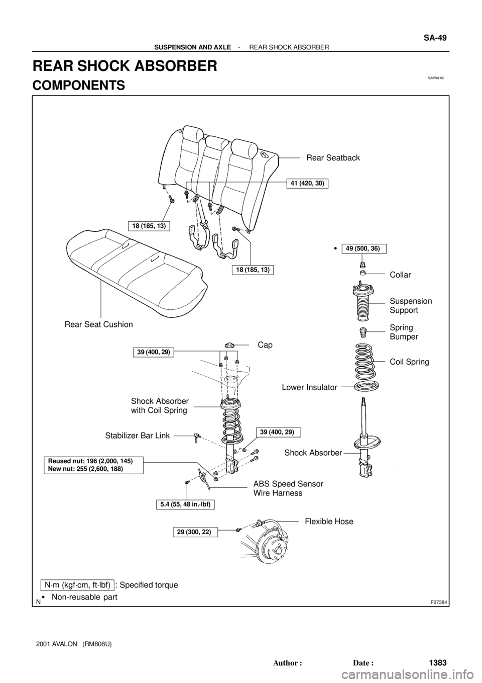
N´m (kgf´cm, ft´lbf) : Specified torque
� Non-reusable partCap
Shock Absorber Shock Absorber
with Coil Spring
39 (400, 29)Stabilizer Bar LinkCollar
Suspension
Support
Spring
Bumper
Coil Spring
Lower Insulator�
49 (500, 36)
Reused nut: 196 (2,000, 145)
New nut: 255 (2,600, 188)
ABS Speed Sensor
Wire Harness
5.4 (55, 48 in.´lbf)
29 (300, 22)
Flexible HoseRear Seatback
Rear Seat Cushion
39 (400, 29)
18 (185, 13)
18 (185, 13)
41 (420, 30)
- SUSPENSION AND AXLEREAR SHOCK ABSORBER
SA-49
1383 Author�: Date�:
2001 AVALON (RM808U)
REAR SHOCK ABSORBER
COMPONENTS
Page 1888 of 1897

REMOVAL
1. REMOVE REAR SEAT (See page BO-1 19)
2. REMOVE REAR WHEEL
Torque: 103")
SA0WA-02
R00749
F01924
F07383
SA-50
- SUSPENSION AND AXLEREAR SHOCK ABSORBER
1384 Author�: Date�:
2001 AVALON (RM808U)
REMOVAL
1. REMOVE REAR SEAT (See page BO-1 19)
2. REMOVE REAR WHEEL
Torque: 103 N´m (1,050 kgf´cm, 76 ft´lbf)
3. DISCONNECT FLEXIBLE HOSE AND ABS SPEED
SENSOR WIRE HARNESS CLAMP
Remove the 2 bolts and disconnect the flexible hose and ABS
speed sensor wire harness clamp.
Torque:
Flexible hose: 29 N´m (300 kgf´cm, 22 ft´lbf)
ABS speed sensor wire harness:
5.4 N´m (55 kgf´cm, 48 in.´lbf)
4. DISCONNECT STABILIZER BAR LINK FROM SHOCK
ABSORBER (See page SA-63)
5. REMOVE SHOCK ABSORBER WITH COIL SPRING
(a) Loosen the 2 nuts on the lower side of the shock absorber.
Torque:
Reused nut: 196 N´m (2,000 kgf´cm, 145 ft´lbf)
New nut: 255 N´m (2,600 kgf´cm, 188 ft´lbf)
HINT:
At the time of installation, coat the nut's threads with engine oil.
(b) Support the rear axle carrier with a jack.
(c) Remove the cap.
(d) Loosen the nut in the center of the suspension support.
NOTICE:
Do not remove it.
Torque: 49 N´m (500 kgf´cm, 36 ft´lbf)
HINT:
If not disassembling the shock absorber, it is not necessary to
loosen the nut.
(e) Remove the 3 nuts of the suspension support.
Torque: 39 N´m (400 kgf´cm, 29 ft´lbf)
(f) Lower the rear axle carrier and remove the 2 bolts on the
lower side of the shock absorber.
(g) Remove the shock absorber with the coil spring.
Page 1889 of 1897
SA0VK-02
F07397N´m (kgf´cm, ft´lbf) : Specified torque
Bushing
Stabilizer Bar Bracket Stabilizer Bar
Stabilizer Bar Link
19 (195, 14)19 (195, 14)
39 (400, 29)
39 (400, 29)
SA-62
- SUSPENSION AND AXLEREAR STABILIZER BAR
1396 Author�: Date�:
2001 AVALON (RM808U)
REAR STABILIZER BAR
COMPONENTS
Page 1890 of 1897
SA0VM-01
Z00340
SA-64
- SUSPENSION AND AXLEREAR STABILIZER BAR
1398 Author�: Date�:
2001 AVALON (RM808U)
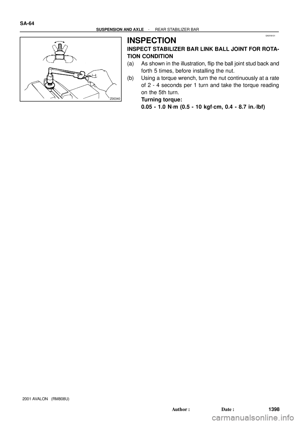
INSPECTION
INSPECT STABILIZER BAR LINK BALL JOINT FOR ROTA-
TION CONDITION
(a) As shown in the illustration, flip the ball joint stud back and
forth 5 times, before installing the nut.
(b) Using a torque wrench, turn the nut continuously at a rate
of 2 - 4 seconds per 1 turn and take the torque reading
on the 5th turn.
Turning torque:
0.05 - 1.0 N´m (0.5 - 10 kgf´cm, 0.4 - 8.7 in.´lbf)
Page 1892 of 1897
SA0VL-02
F06464
W03226
- SUSPENSION AND AXLEREAR STABILIZER BAR
SA-63
1397 Author�: Date�:
2001 AVALON (RM808U)
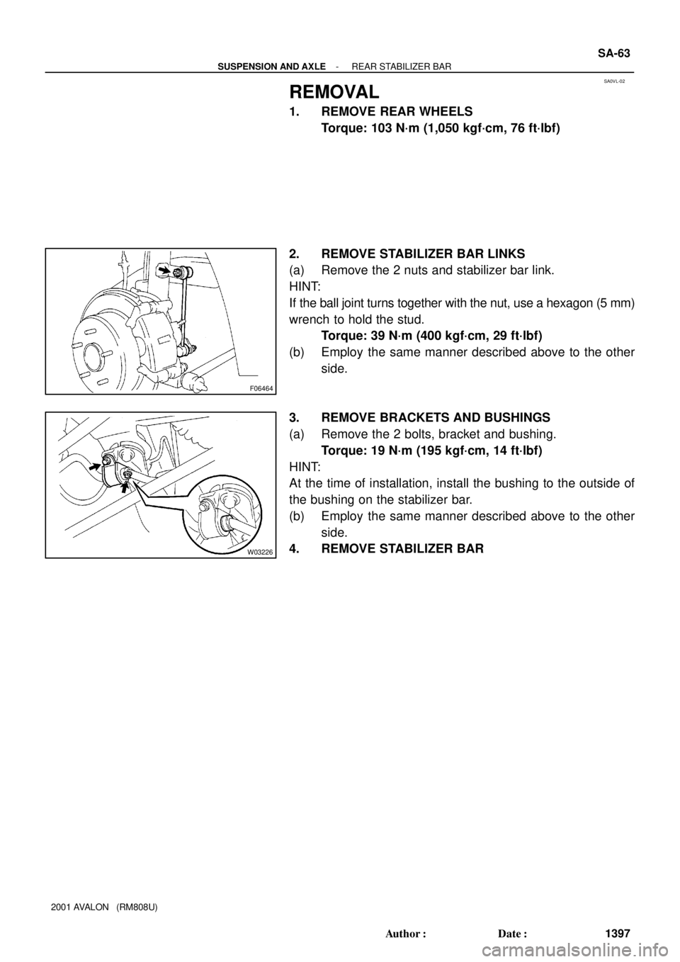
REMOVAL
1. REMOVE REAR WHEELS
Torque: 103 N´m (1,050 kgf´cm, 76 ft´lbf)
2. REMOVE STABILIZER BAR LINKS
(a) Remove the 2 nuts and stabilizer bar link.
HINT:
If the ball joint turns together with the nut, use a hexagon (5 mm)
wrench to hold the stud.
Torque: 39 N´m (400 kgf´cm, 29 ft´lbf)
(b) Employ the same manner described above to the other
side.
3. REMOVE BRACKETS AND BUSHINGS
(a) Remove the 2 bolts, bracket and bushing.
Torque: 19 N´m (195 kgf´cm, 14 ft´lbf)
HINT:
At the time of installation, install the bushing to the outside of
the bushing on the stabilizer bar.
(b) Employ the same manner described above to the other
side.
4. REMOVE STABILIZER BAR
Page 1893 of 1897

REAR WHEEL ALIGNMENT
INSPECTION
1. MEASURE VEHICLE HEIGHT (See pag")
SA1DQ-03
SA3213
Front A
DB
C
F04051
F04052
- SUSPENSION AND AXLEREAR WHEEL ALIGNMENT
SA-7
1341 Author�: Date�:
2001 AVALON (RM808U)
REAR WHEEL ALIGNMENT
INSPECTION
1. MEASURE VEHICLE HEIGHT (See page SA-4)
2. INSTALL CAMBER-CASTER-KINGPIN GAUGE OR
POSITION VEHICLE ON WHEEL ALIGNMENT TES-
TER
Follow the specific instructions of the equipment manufacturer.
3. INSPECT CAMBER
Camber:
Camber
Right-left error-0°43' ± 45' (-0.72° ± 0.75°)
45' (0.75°) or less
If the measured value is not within the specified value, inspect
the suspension parts for damage and/or wear and replace them
if necessary because camber is not adjustable.
4. INSPECT TOE-IN
Toe-in:
Toe-in
(total)A + B: 0°24' ± 12' (0.4° ± 0.2°)
C - D: 4 ± 2 mm (0.16 ± 0.08 in.)
If the toe-in is not within the specified value, adjust it at the
No. 2 lower suspension arm.
5. ADJUST TOE-IN
(a) Measure the lengths of the right and left No. 2 lower sus-
pension arms.
No. 2 lower suspension arm length difference:
1 mm (0.04 in.) or less
If the right-left difference is greater than the specified value, ad-
just the length.
(b) Loosen the lock nuts.
(c) Turn the right and left adjusting tube by an equal amount
to adjust toe-in.
HINT:
�Try to adjust the toe-in to the center value.
�One turn of the each adjusting tube will adjust the toe-in
by about 36' (0.6°, 6.7 mm, 0.264 in.).
(d) Torque the lock nuts.
Torque: 56 N´m (570 kgf´cm, 41 ft´lbf)
Page 1894 of 1897
SA0W8-02
Z00212
SST
Z00213
Nut
Washer
SA-48
- SUSPENSION AND AXLEREAR WHEEL HUB BOLT
1382 Author�: Date�:
2001 AVALON (RM808U)
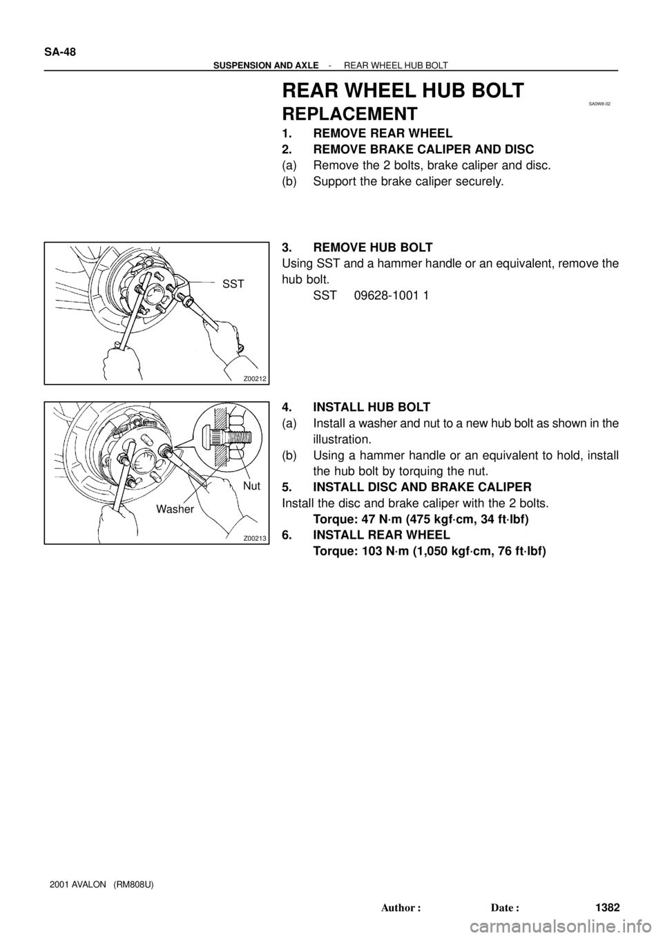
REAR WHEEL HUB BOLT
REPLACEMENT
1. REMOVE REAR WHEEL
2. REMOVE BRAKE CALIPER AND DISC
(a) Remove the 2 bolts, brake caliper and disc.
(b) Support the brake caliper securely.
3. REMOVE HUB BOLT
Using SST and a hammer handle or an equivalent, remove the
hub bolt.
SST 09628-1001 1
4. INSTALL HUB BOLT
(a) Install a washer and nut to a new hub bolt as shown in the
illustration.
(b) Using a hammer handle or an equivalent to hold, install
the hub bolt by torquing the nut.
5. INSTALL DISC AND BRAKE CALIPER
Install the disc and brake caliper with the 2 bolts.
Torque: 47 N´m (475 kgf´cm, 34 ft´lbf)
6. INSTALL REAR WHEEL
Torque: 103 N´m (1,050 kgf´cm, 76 ft´lbf)
 : Specified torque
Bushing
Stabilizer Bar Bracket Stabilizer Bar
Stabilizer Bar Link
19 (195, 14)19 (195, 14)
39 (400, 29)
39 (400, 29)
SA-62
- SUSPENSION AND AX")