Page 1855 of 1897
SA0V7-02
F02225
F02226
F02227
- SUSPENSION AND AXLEFRONT LOWER SUSPENSION ARM
SA-33
1367 Author�: Date�:
2001 AVALON (RM808U)
REMOVAL
1. REMOVE FRONT WHEEL
Torque: 103 N´m (1,050 kgf´cm, 76 ft´lbf)
2. DISCONNECT LOWER SUSPENSION ARM FROM
LOWER BALL JOINT
Remove the 2 nuts and bolt, and disconnect the lower suspen-
sion arm from the lower ball joint.
Torque: 127 N´m (1,300 kgf´cm, 94 ft´lbf)
3. REMOVE LOWER SUSPENSION ARM
(a) Remove the 2 bolts on the front side of the lower suspen-
sion arm.
Torque: 206 N´m (2,100 kgf´cm, 152 ft´lbf)
(b) Remove the bolt and nut on the rear side of the lower sus-
pension arm.
Torque: 206 N´m (2,100 kgf´cm, 152 ft´lbf)
(c) Remove the lower suspension arm.
(d) Remove the lower suspension arm bushing stopper from
the lower suspension arm.
Page 1857 of 1897
SA0UZ-02
F07387
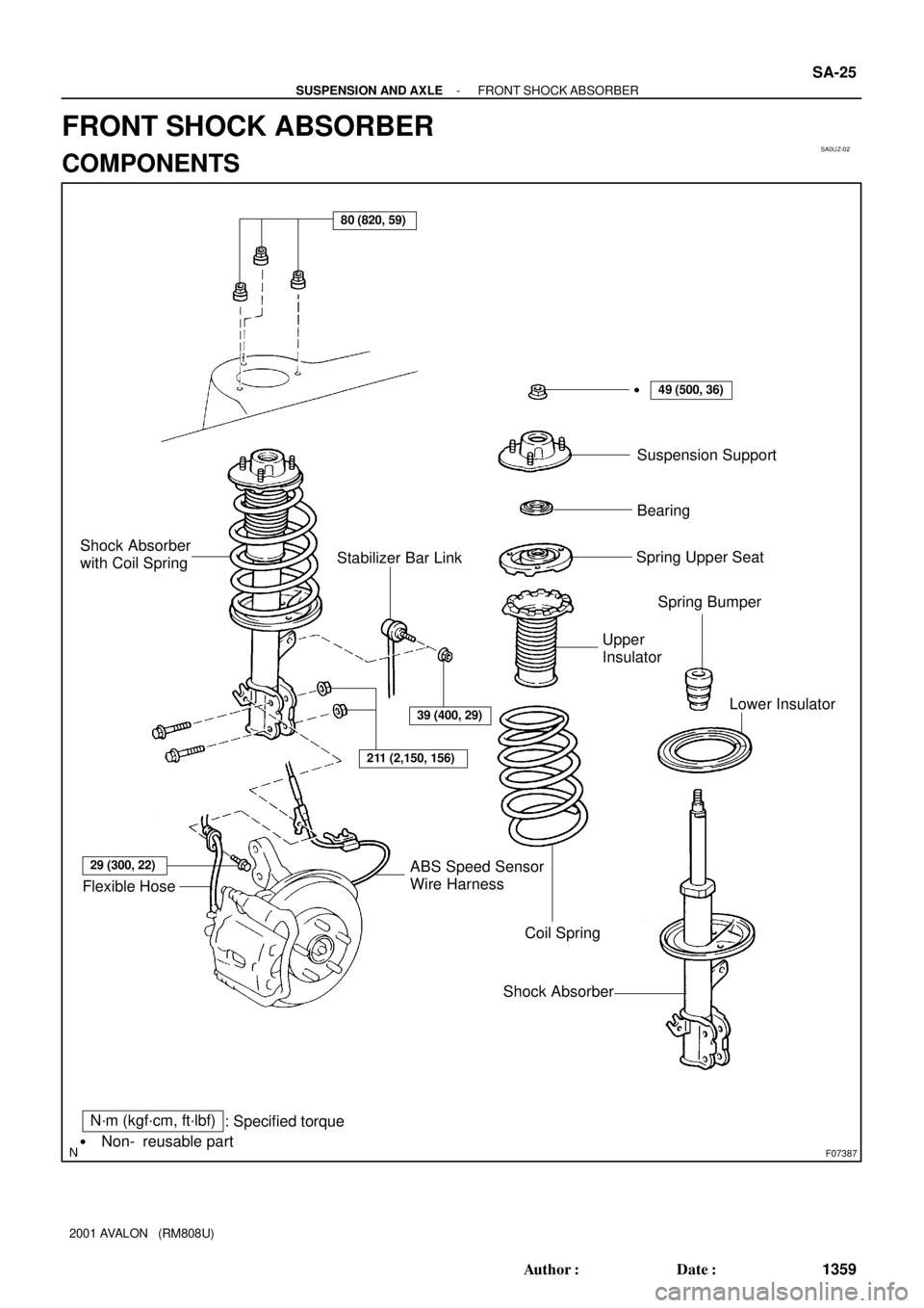
N´m (kgf´cm, ft´lbf)
: Specified torque
Non- reusable part
�
80 (820, 59)
39 (400, 29)
211 (2,150, 156)
29 (300, 22)
Flexible HoseABS Speed Sensor
Wire Harness
Coil Spring
Shock AbsorberLower Insulator Upper
InsulatorSpring Bumper Spring Upper SeatBearing Suspension Support �
Stabilizer Bar Link Shock Absorber
with Coil Spring
49 (500, 36)
- SUSPENSION AND AXLEFRONT SHOCK ABSORBER
SA-25
1359 Author�: Date�:
2001 AVALON (RM808U)
FRONT SHOCK ABSORBER
COMPONENTS
Page 1862 of 1897

REASSEMBLY
1. INSTALL LOWER INSULATOR ONTO SHOCK AB-
SORBER
2. INSTALL")
SA0V4-02
W03200
SST
W03201
W03199
SST SA-30
- SUSPENSION AND AXLEFRONT SHOCK ABSORBER
1364 Author�: Date�:
2001 AVALON (RM808U)
REASSEMBLY
1. INSTALL LOWER INSULATOR ONTO SHOCK AB-
SORBER
2. INSTALL SPRING BUMPER TO PISTON ROD
3. INSTALL COIL SPRING
(a) Using 2 SST of the same type, compress the coil spring.
SST 09727-30021
NOTICE:
Do not use an impact wrench. It will damage the SST.
(b) Install the coil spring to the shock absorber.
HINT:
Fit the lower end of the coil spring into the gap of the spring low-
er seat.
4. INSTALL SPRING UPPER SEAT AND INSULATOR
(a) Align the 'OUT' mark of spring upper seat with the mark
of the upper insulator.
(b) Install the spring upper seat with upper insulator to the
shock absorber with the mark facing to the outside of the
vehicle.
(c) Install the bearing and suspension support.
(d) Using SST to hold the suspension support, install a new
nut.
SST 09729-22031
Torque: 49 N´m (500 kgf´cm, 36 ft´lbf)
(e) Remove the 2 SST from the coil spring.
NOTICE:
Check that the bearing fits into the recess in the suspen-
sion support.
Page 1863 of 1897

REMOVAL
1. REMOVE FRONT WHEEL
Torque: 103 N´m (1,050 kgf´cm, 76 ft´lbf)
2. DIS")
SA0V0-02
F07388
To outside SA-26
- SUSPENSION AND AXLEFRONT SHOCK ABSORBER
1360 Author�: Date�:
2001 AVALON (RM808U)
REMOVAL
1. REMOVE FRONT WHEEL
Torque: 103 N´m (1,050 kgf´cm, 76 ft´lbf)
2. DISCONNECT FLEXIBLE HOSE AND ABS SPEED
SENSOR WIRE HARNESS CLAMP
Remove the bolt and disconnect the flexible hose and ABS
speed sensor wire harness clamp from the shock absorber.
Torque: 29 N´m (300 kgf´cm, 22 ft´lbf)
3. DISCONNECT STABILIZER BAR LINK FROM SHOCK
ABSORBER (See page SA-41)
4. DISCONNECT SHOCK ABSORBER FROM STEERING
KNUCKLE
(a) Remove the 2 nuts and bolts on the lower side of the
shock absorber.
Torque: 211 N´m (2,150 kgf´cm, 156 ft´lbf)
(b) Remove the shock absorber from the steering knuckle.
HINT:
At the time of installation, coat the nut's threads with engine oil.
5. REMOVE SHOCK ABSORBER WITH COIL SPRING
Remove the 3 nuts and shock absorber with the coil spring.
Torque: 80 N´m (820 kgf´cm, 59 ft´lbf)
HINT:
At the time of installation, rotate the suspension support and set
it in the direction, as shown.
Page 1864 of 1897
SA0W2-02
F06453N´m (kgf´cm, ft´lbf) : Specified torque
39 (400, 29)19 (195, 14)
Bracket
Bushing Stabilizer
Bar Link
39 (400, 29)
Stabilizer Bar
39 (400, 29)
39 (400, 29)
BushingBracket
Stabilizer Bar Link
19 (195, 14)
SA-40
- SUSPENSION AND AXLEFRONT STABILIZER BAR
1374 Author�: Date�:
2001 AVALON (RM808U)
FRONT STABILIZER BAR
COMPONENTS
Page 1865 of 1897
SA0W4-01
Z00340
SA-42
- SUSPENSION AND AXLEFRONT STABILIZER BAR
1376 Author�: Date�:
2001 AVALON (RM808U)
INSPECTION
INSPECT STABILIZER BAR LINK BALL JOINT FOR ROTA-
TION CONDITION
(a) As shown in the illustration, flip the ball joint stud back and
forth 5 times, before installing the nut.
(b) Using a torque wrench, turn the nut continuously at a rate
of 2 - 4 seconds per 1 turn and take the torque reading
on the 5th turn.
Turning torque:
0.05 - 1.0 N´m (0.5 - 10 kgf´cm, 0.4 - 8.7 in.´lbf)
Page 1867 of 1897
SA0W3-02
F06454
F06456
- SUSPENSION AND AXLEFRONT STABILIZER BAR
SA-41
1375 Author�: Date�:
2001 AVALON (RM808U)
REMOVAL
1. REMOVE FRONT WHEELS
Torque: 103 N´m (1,050 kgf´cm, 76 ft´lbf)
2. REMOVE STABILIZER BAR LINKS
(a) Remove the 2 nuts and stabilizer bar link.
Torque: 39 N´m (400 kgf´cm, 29 ft´lbf)
HINT:
If the ball joint turns together with the nut, use a hexagon (5 mm)
wrench to hold the stud.
(b) Employ the same manner described above to the other
side.
3. REMOVE BRACKETS AND BUSHINGS
(a) Remove the 2 bolts, bracket and bushing.
Torque: 19 N´m (195 kgf´cm, 14 ft´lbf)
HINT:
At the time of installation, install the bushing to the inside of the
bushing stopper on the stabilizer bar.
(b) Employ the same manner described above to the other
side.
4. REMOVE STABILIZER BAR
Remove the stabilizer bar from the left hand side.
NOTICE:
Be careful not to damage the pressure feed tube.
Page 1869 of 1897

F04031
F04048
1
2
F01195
Bolt
Adjusting
ValueSet Bolt
15'
30'Adjusting Bolt90105-17001 90105-17003 90105-17004 90105-17005
45'
1°00'
1°15'
1°30'121212121 Dot
2 Dots3 Dots
- SUSPENSION AND AXLEFRONT WHEEL ALIGNMENT
SA-5
1339 Author�: Date�:
2001 AVALON (RM808U)
4. ADJUST CAMBER
NOTICE:
After the camber has been adjusted, inspect the toe-in.
(a) Remove the front wheel and ABS speed sensor clamp.
(b) Remove the 2 nuts on the lower side of the shock absorb-
er.
(c) Coat the threads of the nuts with engine oil.
(d) Temporarily install the 2 nuts.
(e) Adjust the camber by pushing or pulling the lower side of
the shock absorber in the direction in which the camber
adjustment is required.
(f) Tighten the nuts.
Torque: 211 N´m (2,150 kgf´cm, 156 ft´lbf)
(g) Install the ABS speed sensor clamp and front wheel.
Torque: 103 N´m (1,050 kgf´cm, 76 ft´lbf)
(h) Check the camber.
HINT:
�Try to adjust the camber to the center of the specified val-
ue.
�Adjusting value for the set bolts is 6' - 30' (0.1° - 0.5°).
If the camber is not within the specified value, using the follow-
ing table, estimate how much additional camber adjustment will
be required, and select the camber adjusting bolt.
(i) Do the steps mentioned above again. Between step (b)
and (c), replace 1 or 2 selected bolts.
HINT:
When replacing the 2 bolts, replace 1 bolt for each time.

 : Specified torque
39 (400, 29)19 (195, 14)
Bracket
Bushing Stabilizer
Bar Link
39 (400, 29)
Stabilizer Bar
39 (400, 29)
39 (400, 29)
BushingBracket
Stabilizer B")