Page 1870 of 1897

5. INSPECT TOE-IN
Toe-in:
Toe-in")
SA3213
Front A
DB
C
F02245
F02246
SA0028
Front AB
A B
A: Inside
B: Outside SA-6
- SUSPENSION AND AXLEFRONT WHEEL ALIGNMENT
1340 Author�: Date�:
2001 AVALON (RM808U)
5. INSPECT TOE-IN
Toe-in:
Toe-in
(total)A + B: 0° ± 12' (0° ± 0.2°)
C - D: 0 ± 2 mm (0 ± 0.08 in.)
If the toe-in is not within the specified value, adjust it at the rack
ends.
6. ADJUST TOE-IN
(a) Remove the rack boot set clips.
(b) Loosen the tie rod end lock nuts.
(c) Turn the right and left rack ends by an equal amount to
adjust the toe-in.
HINT:
Try to adjust the toe-in to the center of the specified value.
(d) Make sure that the lengths of the right and left rack ends
are the same.
Rack end length difference: 1.5 mm (0.059 in.) or less
(e) Torque the tie rod end lock nuts.
Torque: 74 N´m (750 kgf´cm, 54 ft´lbf)
(f) Place the boots on the seats and install the clips.
HINT:
Make sure that the boots are not twisted.
7. INSPECT WHEEL ANGLE
Turn the steering wheel fully, and measure the turning angle.
Wheel turning angle:
Inside wheel35°45' ± 1° (35.75° ± 1°)
Outside wheel: Reference31°23' (31.38°)
If the right and left inside wheel angles differ from the specified
value, check the right and left rack end lengths.
Page 1871 of 1897
SA0VW-02
W03096
SST
W03097
WasherNut SA-14
- SUSPENSION AND AXLEFRONT WHEEL HUB BOLT
1348 Author�: Date�:
2001 AVALON (RM808U)
FRONT WHEEL HUB BOLT
REPLACEMENT
1. REMOVE FRONT WHEEL
2. REMOVE BRAKE CALIPER AND DISC
(a) Remove the 2 bolts, brake caliper and disc.
(b) Support the brake caliper securely.
3. REMOVE HUB BOLT
Using SST and a hammer handle or an equivalent, remove the
hub bolt.
SST 09628-1001 1
4. INSTALL HUB BOLT
(a) Install a washer and nut to a new hub bolt, as shown in the
illustration.
(b) Using a hammer handle or an equivalent to hold, install
the hub bolt by torquing the nut.
5. INSTALL DISC AND BRAKE CALIPER
Install the disc and brake caliper with the 2 bolts.
Torque: 107 N´m (1,090 kgf´cm, 79 ft´lbf)
6. INSTALL FRONT WHEEL
Torque: 103 N´m (1,050 kgf´cm, 76 ft´lbf)
Page 1872 of 1897
SA0ER-03
F08681
Rear Axle CarrierNo.2 Lower
Suspension Arm
Brake Caliper
Rear Axle Hub Hub Bolt
Strut Rod ABS
Speed Sensor No.1 Lower
Suspension Arm
O-Ring
N´m (kgf´cm, ft´lbf) : Specified torque
Non-reusable part �Disc �
Reused Nut : 196 (2,000, 145)
New Nut : 255 (2,600, 188)
80 (820, 59)
181 (1,850, 134)
47 (475, 34)
8.0 (82, 71 in.´lbf)
113 (1,150, 83)
SA-44
- SUSPENSION AND AXLEREAR AXLE HUB
1378 Author�: Date�:
2001 AVALON (RM808U)
REAR AXLE HUB
COMPONENTS
Page 1874 of 1897

REMOVAL
1. REMOVE REAR WHEEL
Torque: 103 N´m (1,050 kgf´cm, 76 ft´lbf)
2. R")
SA0W6-02
R10948
Z00206
W03211
A
A
B
- SUSPENSION AND AXLEREAR AXLE HUB
SA-45
1379 Author�: Date�:
2001 AVALON (RM808U)
REMOVAL
1. REMOVE REAR WHEEL
Torque: 103 N´m (1,050 kgf´cm, 76 ft´lbf)
2. REMOVE BRAKE CALIPER AND DISC
(a) Remove the brake caliper and disc.
Torque: 47 N´m (475 kgf´cm, 34 ft´lbf)
(b) Support the brake caliper securely.
3. CHECK BEARING BACKLASH AND AXLE HUB DEVI-
ATION
(a) Using a dial indicator, check the backlash near the center
of the axle hub.
Maximum: 0.05 mm (0.0020 in.)
If the backlash exceeds the maximum, replace the axle hub.
(b) Using a dial indicator, check the deviation at the surface
of the axle hub outside the hub bolt.
Maximum: 0.07 mm (0.0028 in.)
If the deviation exceeds the maximum, replace the axle hub.
4. DISCONNECT ABS SPEED SENSOR
Remove the bolt and disconnect the ABS speed sensor.
Torque: 8.0 N´m (82 kgf´cm, 71 in.´lbf)
5. REMOVE REAR AXLE HUB
(a) Remove the 4 bolts and rear axle hub.
Torque: 80 N´m (820 kgf´cm, 59 ft´lbf)
(b) Remove the O-ring.
HINT:
At the time of installation, coat a new O-ring with MP grease.
(c) Support the backing plate securely.
6. REMOVE REAR AXLE CARRIER
(a) Loosen the 3 nuts.
Torque:
Nut A (Reused nut): 196 N´m (2,000 kgf´cm, 145 ft´lbf)
Nut A (New nut): 255 N´m (2,600 kgf´cm, 188 ft´lbf)
Nut B: 181 N´m (1,850 kgf´cm, 134 ft´lbf)
Page 1875 of 1897
R11165
SA-46
- SUSPENSION AND AXLEREAR AXLE HUB
1380 Author�: Date�:
2001 AVALON (RM808U)
HINT:
At the time of installation, please refer to the following items.
�After stabilizing the suspension, torque the nuts.
�If reusing the 2 nuts A, coat the nut's threads with engine
oil.
(b) Remove the bolt and nut, and disconnect the strut rod
from the rear axle carrier.
NOTICE:
Do not turn the nut.
Torque: 113 N´m (1,150 kgf´cm, 83 ft´lbf)
(c) Remove the 2 nuts and bolts on the lower side of the
shock absorber.
(d) Remove the nut, washer and bolt and disconnect the No.
1 and No. 2 lower suspension arm from the rear axle carri-
er.
(e) Remove the rear axle carrier.
Page 1876 of 1897
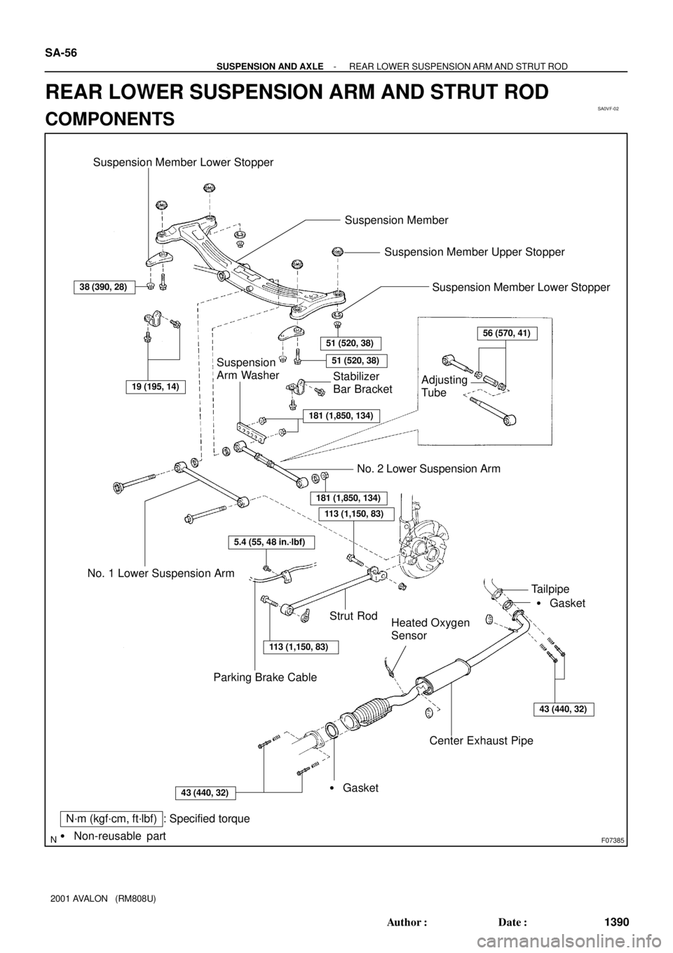
SA0VF-02
F07385
N´m (kgf´cm, ft´lbf) : Specified torque
Non-reusable part �
38 (390, 28)
51 (520, 38)
51 (520, 38)
56 (570, 41)
181 (1,850, 134)
19 (195, 14)
181 (1,850, 134)
113 (1,150, 83)
5.4 (55, 48 in.´lbf)
113 (1,150, 83)
43 (440, 32)
Suspension Member Lower Stopper Suspension Member Lower Stopper
Suspension Member
Adjusting
TubeStabilizer
Bar Bracket
Suspension
Arm Washer
No. 2 Lower Suspension Arm
No. 1 Lower Suspension Arm
Parking Brake Cable
Strut Rod
Heated Oxygen
Sensor
� Gasket Tailpipe
Center Exhaust Pipe
� GasketSuspension Member Upper Stopper43 (440, 32)
SA-56
- SUSPENSION AND AXLEREAR LOWER SUSPENSION ARM AND STRUT ROD
1390 Author�: Date�:
2001 AVALON (RM808U)
REAR LOWER SUSPENSION ARM AND STRUT ROD
COMPONENTS
Page 1879 of 1897
SA1F9-02
F06460
W03223
AB
F06462
SA-60
- SUSPENSION AND AXLEREAR LOWER SUSPENSION ARM AND STRUT ROD
1394 Author�: Date�:
2001 AVALON (RM808U)
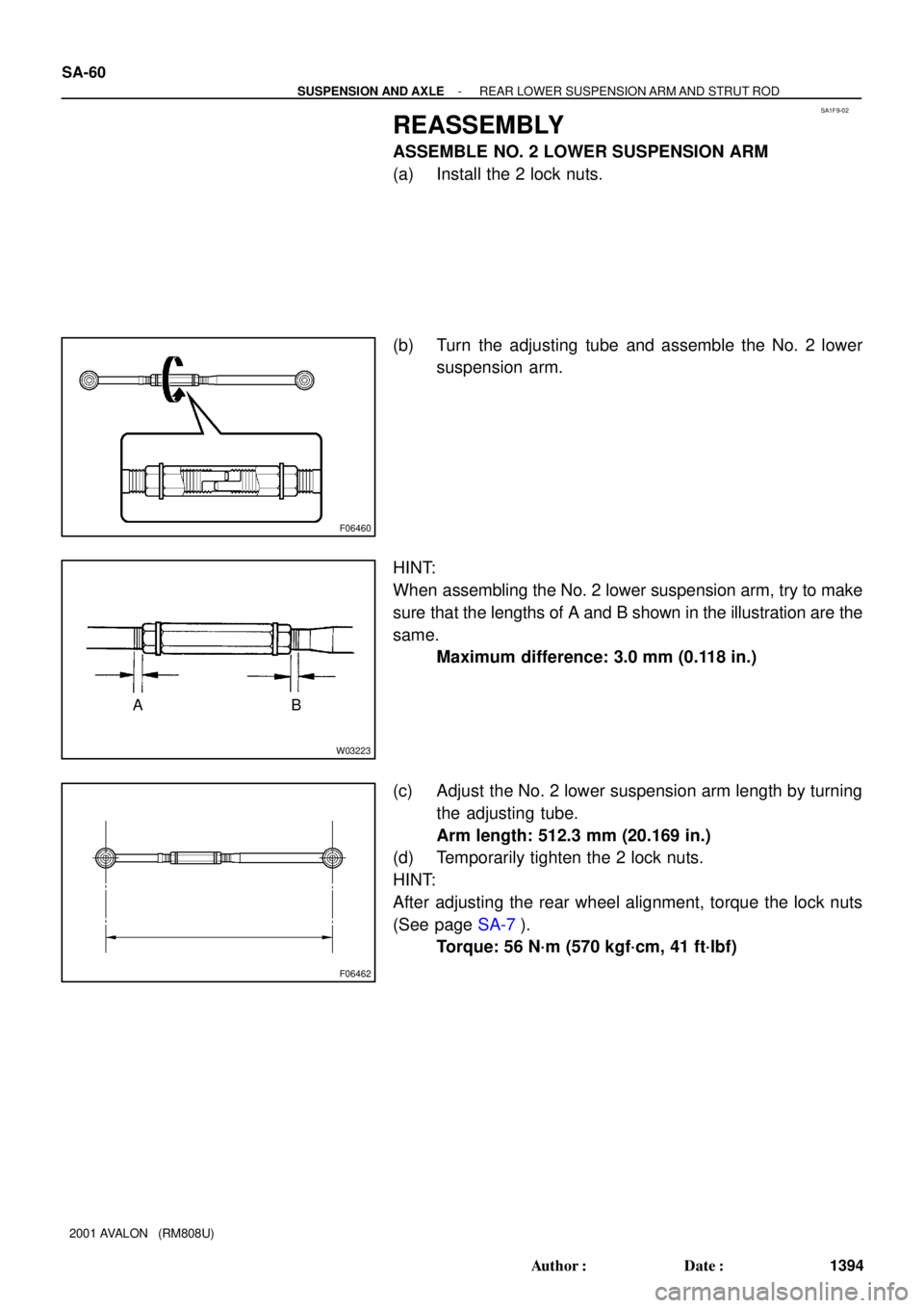
REASSEMBLY
ASSEMBLE NO. 2 LOWER SUSPENSION ARM
(a) Install the 2 lock nuts.
(b) Turn the adjusting tube and assemble the No. 2 lower
suspension arm.
HINT:
When assembling the No. 2 lower suspension arm, try to make
sure that the lengths of A and B shown in the illustration are the
same.
Maximum difference: 3.0 mm (0.118 in.)
(c) Adjust the No. 2 lower suspension arm length by turning
the adjusting tube.
Arm length: 512.3 mm (20.169 in.)
(d) Temporarily tighten the 2 lock nuts.
HINT:
After adjusting the rear wheel alignment, torque the lock nuts
(See page SA-7).
Torque: 56 N´m (570 kgf´cm, 41 ft´lbf)
Page 1880 of 1897

REMOVAL
1. REMOVE REAR WHEEL
Torque: 103 N´m (")
SA0VG-02
W03216
W03217
Rear
F06465A
A B
B
- SUSPENSION AND AXLEREAR LOWER SUSPENSION ARM AND STRUT ROD
SA-57
1391 Author�: Date�:
2001 AVALON (RM808U)
REMOVAL
1. REMOVE REAR WHEEL
Torque: 103 N´m (1,050 kgf´cm, 76 ft´lbf)
2. REMOVE CENTER EXHAUST PIPE
3. REMOVE STRUT ROD
(a) Remove the bolt and disconnect the parking brake cable.
Torque: 5.4 N´m (55 kgf´cm, 48 in.´lbf)
(b) Remove the 2 bolts and nuts.
Torque: 113 N´m (1,150 kgf´cm, 83 ft´lbf)
NOTICE:
Do not turn the nut.
HINT:
At the time of installation, after stabilizing the suspension,
torque the bolts.
(c) Remove the strut rod.
4. REMOVE NO. 2 LOWER SUSPENSION ARM
(a) Remove the 3 nuts, suspension arm washer and washer.
Torque: 181 N´m (1,850 kgf´cm, 134 ft´lbf)
HINT:
At the time of installation, after stabilizing the suspension,
torque the nuts.
(b) Remove the No. 2 lower suspension arm.
HINT:
At the time of installation, face the paint mark to the rearward.
5. REMOVE STABILIZER BAR BRACKETS
(See page SA-63)
6. REMOVE NO. 1 LOWER SUSPENSION ARM
(a) Support the suspension member with a jack.
(b) Remove the 4 nuts, 2 bolts and 8 suspension member
stoppers.
Torque:
A: 51 N´m (520 kgf´cm, 38 ft´lbf)
B: 38 N´m (390 kgf´cm, 28 ft´lbf)
(c) Lower the suspension member.

 : Specified torque")