Page 1838 of 1897
W03094
SST
F02207
SA-10
- SUSPENSION AND AXLEFRONT AXLE HUB
1344 Author�: Date�:
2001 AVALON (RM808U)
6. DISCONNECT TIE ROD END FROM STEERING
KNUCKLE
(a) Remove the cotter pin and nut.
Torque: 49 N´m (500 kgf´cm, 36 ft´lbf)
(b) Using SST, disconnect the tie rod end from the steering
knuckle.
SST 09610-20012
7. DISCONNECT LOWER BALL JOINT FROM LOWER
SUSPENSION ARM
Remove the 2 nuts and bolt.
Torque: 127 N´m (1,300 kgf´cm, 94 ft´lbf)
8. REMOVE STEERING KNUCKLE WITH AXLE HUB
(a) Remove the 2 nuts and bolts on the lower side of the
shock absorber.
(b) Remove the steering knuckle with the axle hub.
NOTICE:
Be careful not to damage the boot and ABS speed sensor
rotor.
Page 1839 of 1897
SA0VX-02
F07396
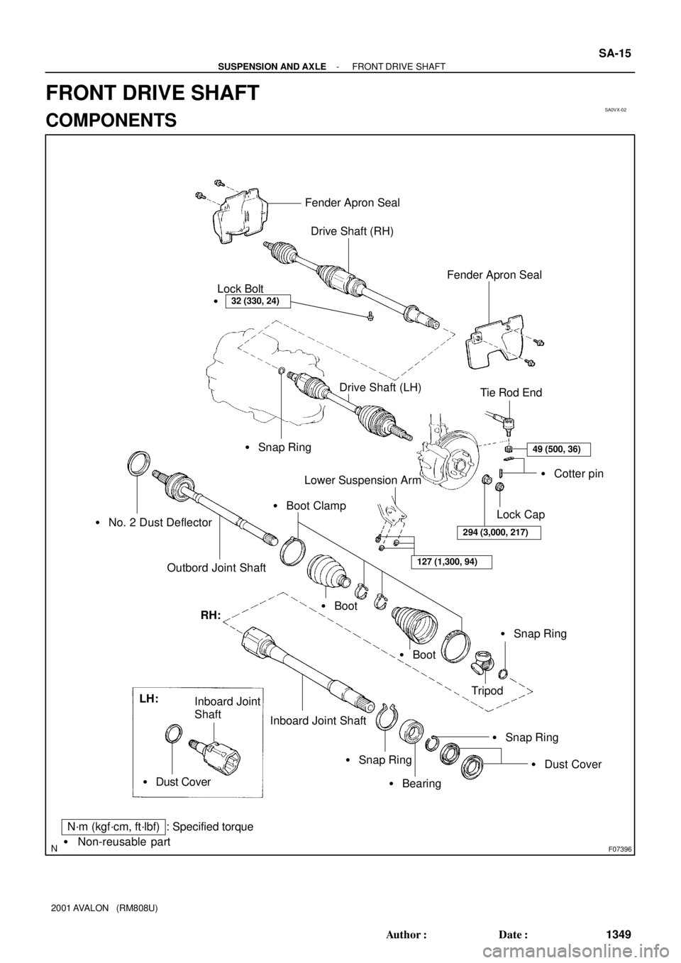
Fender Apron Seal
Drive Shaft (RH)
32 (330, 24)�Lock Bolt
� Snap Ring
� No. 2 Dust Deflector
Outbord Joint Shaft
Fender Apron Seal
Tie Rod End
49 (500, 36)
� Cotter pin
Lock Cap
294 (3,000, 217)
Lower Suspension Arm
127 (1,300, 94)
� Boot Clamp
� Boot
� Boot
� Snap Ring
Tripod RH:
Inboard Joint Shaft
� Snap Ring
� Bearing
� Snap Ring
� Dust Cover LH:
Inboard Joint
Shaft
� Dust Cover
N´m (kgf´cm, ft´lbf) : Specified torque
� Non-reusable part
Drive Shaft (LH)
- SUSPENSION AND AXLEFRONT DRIVE SHAFT
SA-15
1349 Author�: Date�:
2001 AVALON (RM808U)
FRONT DRIVE SHAFT
COMPONENTS
Page 1847 of 1897

REMOVAL
NOTICE:
�The hub bearing could be damaged if it is subjected
t")
SA0VY-02
FA1535
SST
W03093
W03142
F07389
SA-16
- SUSPENSION AND AXLEFRONT DRIVE SHAFT
1350 Author�: Date�:
2001 AVALON (RM808U)
REMOVAL
NOTICE:
�The hub bearing could be damaged if it is subjected
to the vehicle weight, such as when moving the ve-
hicle with the drive shaft removed.
Therefore, if it is absolutely necessary to place the ve-
hicle weight on the hub bearing, first support it with
SST.
SST 09608-16042 (09608-02021, 09608-02041)
�After disconnecting the drive shaft from the axle hub,
work carefully so as not to damage the ABS speed
sensor rotor serration on the drive shaft.
1. REMOVE FRONT WHEEL
Torque: 103 N´m (1,050 kgf´cm, 76 ft´lbf)
2. REMOVE FRONT FENDER APRON SEAL
3. DRAIN ATF
4. REMOVE DRIVE SHAFT LOCK NUT
(a) Remove the cotter pin and lock cap.
(b) While applying brakes, remove the nut.
Torque: 294 N´m (3,000 kgf´cm, 217 ft´lbf)
5. DISCONNECT TIE ROD END FROM STEERING
KNUCKLE (See page SA-9)
6. DISCONNECT LOWER SUSPENSION ARM FROM
LOWER BALL JOINT (See page SA-9)
7. DISCONNECT DRIVE SHAFT FROM AXLE HUB
Using a plastic hammer, disconnect the drive shaft from the axle
hub.
NOTICE:
Be careful not to damage the boot and ABS speed sensor
rotor.
8. LH drive shaft:
REMOVE DRIVE SHAFT
(a) Using a hub nut wrench and hammer handle or an equiva-
lent, remove the drive shaft.
NOTICE:
Be careful not to damage the dust cover and oil seal.
Page 1848 of 1897

HINT:
At the time of installation, please refer to the following items.
�Coat gear oil to the inboard jo")
W03144
- SUSPENSION AND AXLEFRONT DRIVE SHAFT
SA-17
1351 Author�: Date�:
2001 AVALON (RM808U)
HINT:
At the time of installation, please refer to the following items.
�Coat gear oil to the inboard joint shaft and differential
case sliding surface.
�Before installing the drive shaft, set the snap ring opening
side facing downward.
�Whether or not the inboard joint shaft is making contact
with the pinion shaft can be known by the sound or feeling
when driving it in.
�After installation, check that there is 2 - 3 mm (0.08 - 0.12
in.) of play in the axial direction.
�After installation, check that the drive shaft cannot be re-
moved by hand.
(b) Using a screwdriver, remove the snap ring from the in-
board joint shaft.
9. RH drive shaft:
REMOVE DRIVE SHAFT
(a) Remove the bearing lock bolt.
Torque: 32 N´m (330 kgf´cm, 24 ft´lbf)
(b) Using pliers, remove the snap ring and drive shaft.
NOTICE:
Be careful not to damage the dust cover and oil seal.
HINT:
At the time of installation, coat gear oil to the inboard joint shaft
and differential case sliding surface.
Page 1849 of 1897
SA0VA-02
F06451
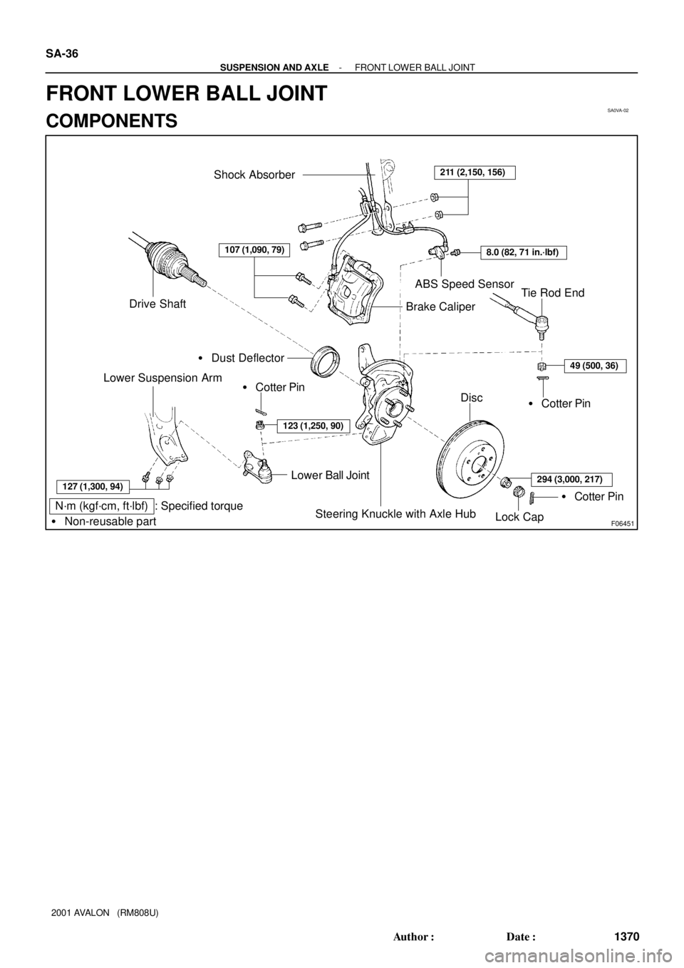
N´m (kgf´cm, ft´lbf) : Specified torque
� Non-reusable part
Shock Absorber211 (2,150, 156)
8.0 (82, 71 in.´lbf)
ABS Speed Sensor
Brake Caliper
49 (500, 36)
� Cotter PinDisc
� Cotter Pin
Steering Knuckle with Axle Hub
Lower Ball Joint
123 (1,250, 90)
� Cotter Pin
127 (1,300, 94)
Lower Suspension Arm
� Dust Deflector
Drive ShaftTie Rod End
Lock Cap
107 (1,090, 79)
294 (3,000, 217)
SA-36
- SUSPENSION AND AXLEFRONT LOWER BALL JOINT
1370 Author�: Date�:
2001 AVALON (RM808U)
FRONT LOWER BALL JOINT
COMPONENTS
Page 1850 of 1897
SA0VC-01
N00208
SA-38
- SUSPENSION AND AXLEFRONT LOWER BALL JOINT
1372 Author�: Date�:
2001 AVALON (RM808U)
INSPECTION
INSPECT LOWER BALL JOINT FOR ROTATION CONDI-
TION
(a) As shown in the illustration, flip the ball joint stud back and
forth 5 times, before installing the nut.
(b) Using a torque wrench, turn the nut continuously at a rate
of 2 - 4 seconds per 1 turn and take the torque reading
on the 5th turn.
Turning torque:
1.0 - 3.4 N´m (10 - 35 kgf´cm, 8.7 - 30 in.´lbf)
Page 1851 of 1897
SA0VD-03
R08850
R08861SSTSST
- SUSPENSION AND AXLEFRONT LOWER BALL JOINT
SA-39
1373 Author�: Date�:
2001 AVALON (RM808U)
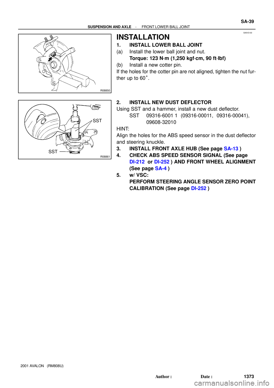
INSTALLATION
1. INSTALL LOWER BALL JOINT
(a) Install the lower ball joint and nut.
Torque: 123 N´m (1,250 kgf´cm, 90 ft´lbf)
(b) Install a new cotter pin.
If the holes for the cotter pin are not aligned, tighten the nut fur-
ther up to 60°.
2. INSTALL NEW DUST DEFLECTOR
Using SST and a hammer, install a new dust deflector.
SST 09316-6001 1 (09316-00011, 09316-00041),
09608-32010
HINT:
Align the holes for the ABS speed sensor in the dust deflector
and steering knuckle.
3. INSTALL FRONT AXLE HUB (See page SA-13)
4. CHECK ABS SPEED SENSOR SIGNAL (See page
DI-212 or DI-252) AND FRONT WHEEL ALIGNMENT
(See page SA-4)
5. w/ VSC:
PERFORM STEERING ANGLE SENSOR ZERO POINT
CALIBRATION (See page DI-252)
Page 1853 of 1897
SA0V6-02
F02228
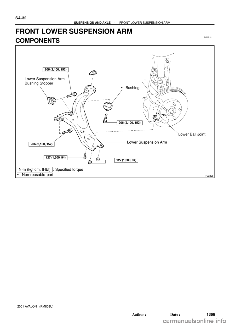
� Bushing
Lower Suspension Arm
Lower Suspension Arm
Bushing Stopper
Lower Ball Joint
N´m (kgf´cm, ft´lbf) : Specified torque
� Non-reusable part
206 (2,100, 152)
206 (2,100, 152)
127 (1,300, 94)127 (1,300, 94)
206 (2,100, 152)
SA-32
- SUSPENSION AND AXLEFRONT LOWER SUSPENSION ARM
1366 Author�: Date�:
2001 AVALON (RM808U)
FRONT LOWER SUSPENSION ARM
COMPONENTS