Page 19 of 1897
AC-10
- AIR CONDITIONINGAIR CONDITIONING SYSTEM
1932 Author�: Date�:
2001 AVALON (RM808U)
4. INSPECT IDLE-UP SPEED
(a) Warm up engine.
(b) Inspect idle-up speed when the these conditions are es-
tablished.
Test conditions:
�Idle speed set correctly.
�Steering wheel straight ahead
�Blower speed control switch at HI
�A/C switch ON
�Steering wheel straight ahead
Magnetic clutch conditionIdle speed
Magnetic clutch not engaged700 ±50 rpm
Magnetic clutch engaged700 ±50 rpm
If idle speed is not as specified, check the IAC valve and idle
control system (See page SF-43,DI-102 ).
Page 97 of 1897
AT3412
AX03Z-05
AX-42
- AUTOMATIC TRANSAXLEAUTOMATIC TRANSAXLE UNIT
1332 Author�: Date�:
2001 AVALON (RM808U)
INSTALLATION
1. CHECK TORQUE CONVERTER CLUTCH INSTALLA-
TION
Using a scale and a straight edge, measure the distance from
the installed surface to the transaxle housing.
Correct distance: 13.7 mm (0.539 in.) or more
2. TRANSAXLE INSTALLATION
Installation is in the reverse order of removal (See page
AX-35).
HINT:
After installation, check and inspect the following items.
�Fill ATF and check fluid level (See page DI-160).
�Check front wheel alignment (See page SA-4).
�Do the road test (See page DI-160).
�Adjust the hood (See page BO-6).
NOTICE:
w/ VSC:
After installation, perform the steering angle sensor zero
point calibration (See page DI-252).
Page 102 of 1897
D02910
P19478
Engine
Hanger
Q06479
- AUTOMATIC TRANSAXLEAUTOMATIC TRANSAXLE UNIT
AX-39
1329 Author�: Date�:
2001 AVALON (RM808U)
30. TIE STEERING GEAR ASSEMBLY WITH CODE OR
EQUIVALENT TO SUSPEND ASSEMBLY SECURELY,
AS SHOWN
31. REMOVE 2 STEERING GEAR ASSEMBLY MOUNTING
BOLTS
Torque: 181 N´m (1,850 kgf´cm, 134 ft´lbf)
32. ATTACH ENGINE SLING DEVICE TO ENGINE HANG-
ERS
(a) Install the No.2 engine hangers in the correct direction.
Part No.:
No.2 engine hanger: 12282-20020
Bolt: 91621-60822
Torque: 20 N´m (200 kgf´cm, 14 ft´lbf)
(b) Attach the engine chain hoist to the engine hangers.
CAUTION:
Do not attempt to hang the engine by hooking the chain to
any other part.
33. REMOVE FRONT FRAME ASSEMBLY
(a) Remove the 2 bolts and PS reservoir pipe mounting
brackets.
Torque: 10 N´m (100 kgf´cm, 7 ft´lbf)
Page 377 of 1897

BO2PU-02
H12194: Specified torqueN´m (kgf´cm, ft´lbf)
AA
KK
K
K
K
K
K
K
B
L
E
G
GG
G
GG
G
GGI
C
C
C
C
K
K
KKB Instrument Panel Reinforcement
No. 2 Instrument
Panel to Cowl BraceFront Pillar Garnish
Upper Cluster Finish Panel
Instrument Panel
Safety Pad Front Pillar GarnishNo. 1 Heater to
Register Duct
Instrument Panel
to Cowl BraceSpeaker Opening
Cover Assembly
H
H
H
H
H
H
III
G
D EDD
Steering Wheel
Floor shift:
Rear Console Box Floor shift:
Front Console Box
Combination Switch No. 1 Lower PanelLH Lower Insert
Column shift:
Finish Panel Hood Lock
Release LeverNo. 2 Under Cover
Floor shift:
Console Box
Plate
Steering Wheel Pad Steering Column
Cover
Floor shift:
Front Ash Receptacle
Floor shift:
Upper Console PanelLower Finish
Panel Column shift:
Lower Cover LH Register
TAIWAN:
Center Cluster
Finish Panel
TAIWAN:
Opening Covers with
Heater Control Assembly Radio Assembly with Heater
Control AssemblyLower Panel
Cluster Finish Panel
End Finish Panel Combination Meter Lower Cluster
Finish PanelGlove Compartment
Door Finish Plate
Speaker Opening
Cover Assembly
No. 2 Heater to
Register Duct
No. 1 Register
Floor shift:
Cup Holder
Multi Information
Display
Floor shift:
Under Rear
Console Panel
I
HH
50 (510, 37)
20 (204, 15)
N
JJJJConsole Box Hole Cover
Column shift:
Front Ash Receptacle
- BODYINSTRUMENT PANEL
BO-87
1872 Author�: Date�:
2001 AVALON (RM808U)
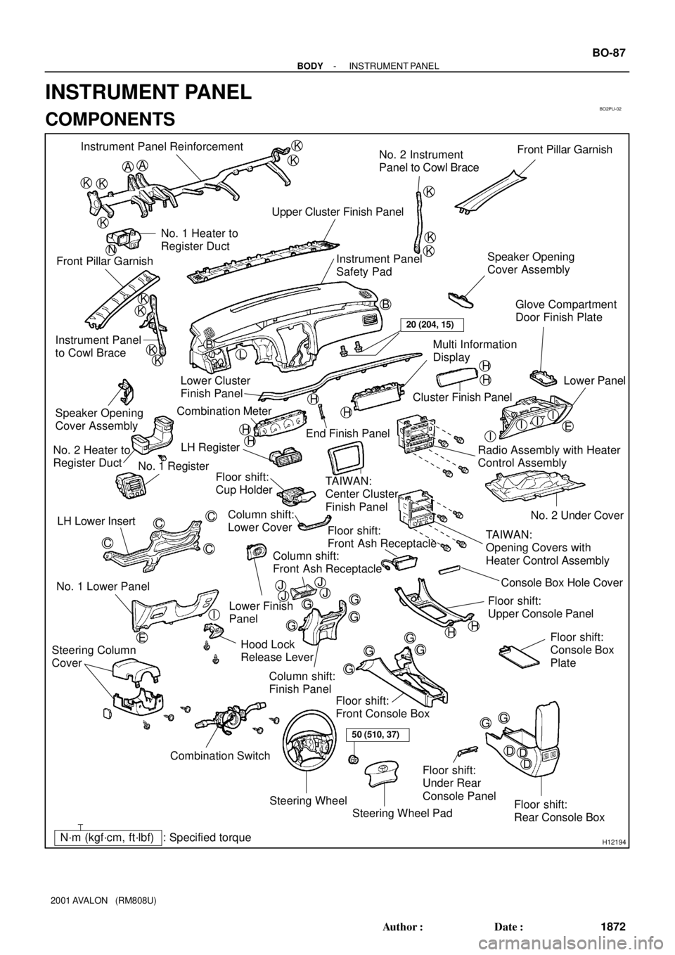
INSTRUMENT PANEL
COMPONENTS
Page 383 of 1897

BO2PV-01
H12176
2 Clips
H121774 Clips
H12178
4 Clips
H12181
BO-90
- BODYINSTRUMENT PANEL
1875 Author�: Date�:
2001 AVALON (RM808U)
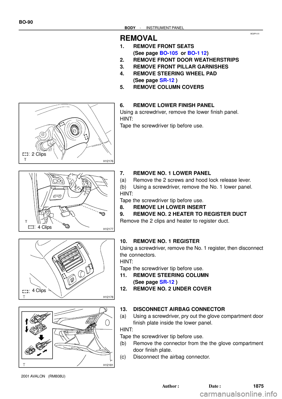
REMOVAL
1. REMOVE FRONT SEATS
(See page BO-105 or BO-1 12)
2. REMOVE FRONT DOOR WEATHERSTRIPS
3. REMOVE FRONT PILLAR GARNISHES
4. REMOVE STEERING WHEEL PAD
(See page SR-12)
5. REMOVE COLUMN COVERS
6. REMOVE LOWER FINISH PANEL
Using a screwdriver, remove the lower finish panel.
HINT:
Tape the screwdriver tip before use.
7. REMOVE NO. 1 LOWER PANEL
(a) Remove the 2 screws and hood lock release lever.
(b) Using a screwdriver, remove the No. 1 lower panel.
HINT:
Tape the screwdriver tip before use.
8. REMOVE LH LOWER INSERT
9. REMOVE NO. 2 HEATER TO REGISTER DUCT
Remove the 2 clips and heater to register duct.
10. REMOVE NO. 1 REGISTER
Using a screwdriver, remove the No. 1 register, then disconnect
the connectors.
HINT:
Tape the screwdriver tip before use.
11. REMOVE STEERING COLUMN
(See page SR-12)
12. REMOVE NO. 2 UNDER COVER
13. DISCONNECT AIRBAG CONNECTOR
(a) Using a screwdriver, pry out the glove compartment door
finish plate inside the lower panel.
HINT:
Tape the screwdriver tip before use.
(b) Remove the connector from the the glove compartment
door finish plate.
(c) Disconnect the airbag connector.
Page 388 of 1897

BO2PU-02
H12194: Specified torqueN´m (kgf´cm, ft´lbf)
AA
KK
K
K
K
K
K
K
B
L
E
G
GG
G
GG
G
GGI
C
C
C
C
K
K
KKB Instrument Panel Reinforcement
No. 2 Instrument
Panel to Cowl BraceFront Pillar Garnish
Upper Cluster Finish Panel
Instrument Panel
Safety Pad Front Pillar GarnishNo. 1 Heater to
Register Duct
Instrument Panel
to Cowl BraceSpeaker Opening
Cover Assembly
H
H
H
H
H
H
III
G
D EDD
Steering Wheel
Floor shift:
Rear Console Box Floor shift:
Front Console Box
Combination Switch No. 1 Lower PanelLH Lower Insert
Column shift:
Finish Panel Hood Lock
Release LeverNo. 2 Under Cover
Floor shift:
Console Box
Plate
Steering Wheel Pad Steering Column
Cover
Floor shift:
Front Ash Receptacle
Floor shift:
Upper Console PanelLower Finish
Panel Column shift:
Lower Cover LH Register
TAIWAN:
Center Cluster
Finish Panel
TAIWAN:
Opening Covers with
Heater Control Assembly Radio Assembly with Heater
Control AssemblyLower Panel
Cluster Finish Panel
End Finish Panel Combination Meter Lower Cluster
Finish PanelGlove Compartment
Door Finish Plate
Speaker Opening
Cover Assembly
No. 2 Heater to
Register Duct
No. 1 Register
Floor shift:
Cup Holder
Multi Information
Display
Floor shift:
Under Rear
Console Panel
I
HH
50 (510, 37)
20 (204, 15)
N
JJJJConsole Box Hole Cover
Column shift:
Front Ash Receptacle
- BODYINSTRUMENT PANEL
BO-87
1872 Author�: Date�:
2001 AVALON (RM808U)
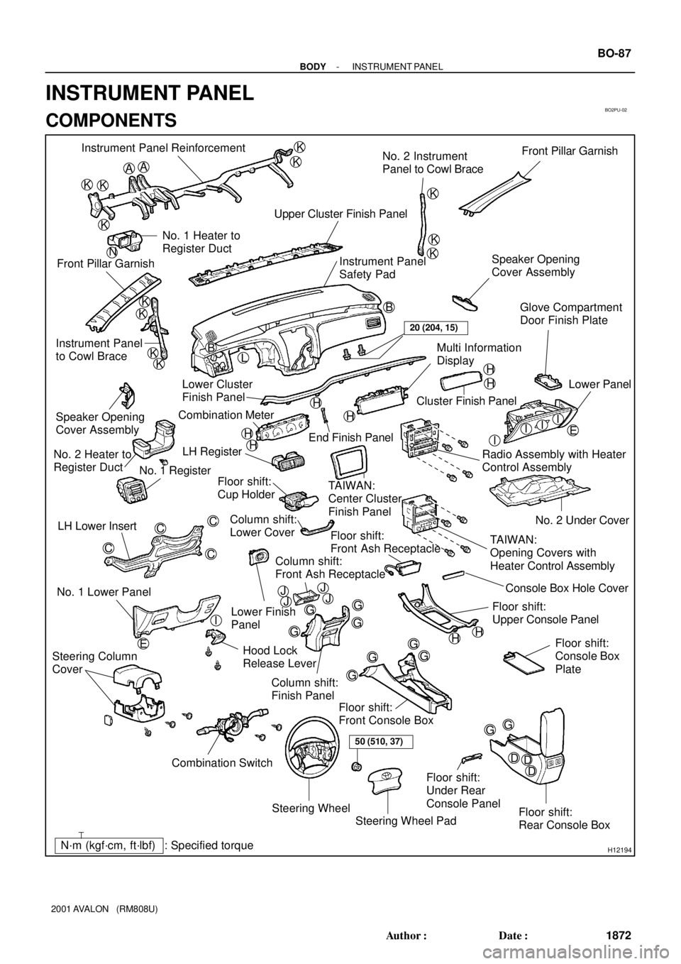
INSTRUMENT PANEL
COMPONENTS
Page 394 of 1897

BO2PV-01
H12176
2 Clips
H121774 Clips
H12178
4 Clips
H12181
BO-90
- BODYINSTRUMENT PANEL
1875 Author�: Date�:
2001 AVALON (RM808U)
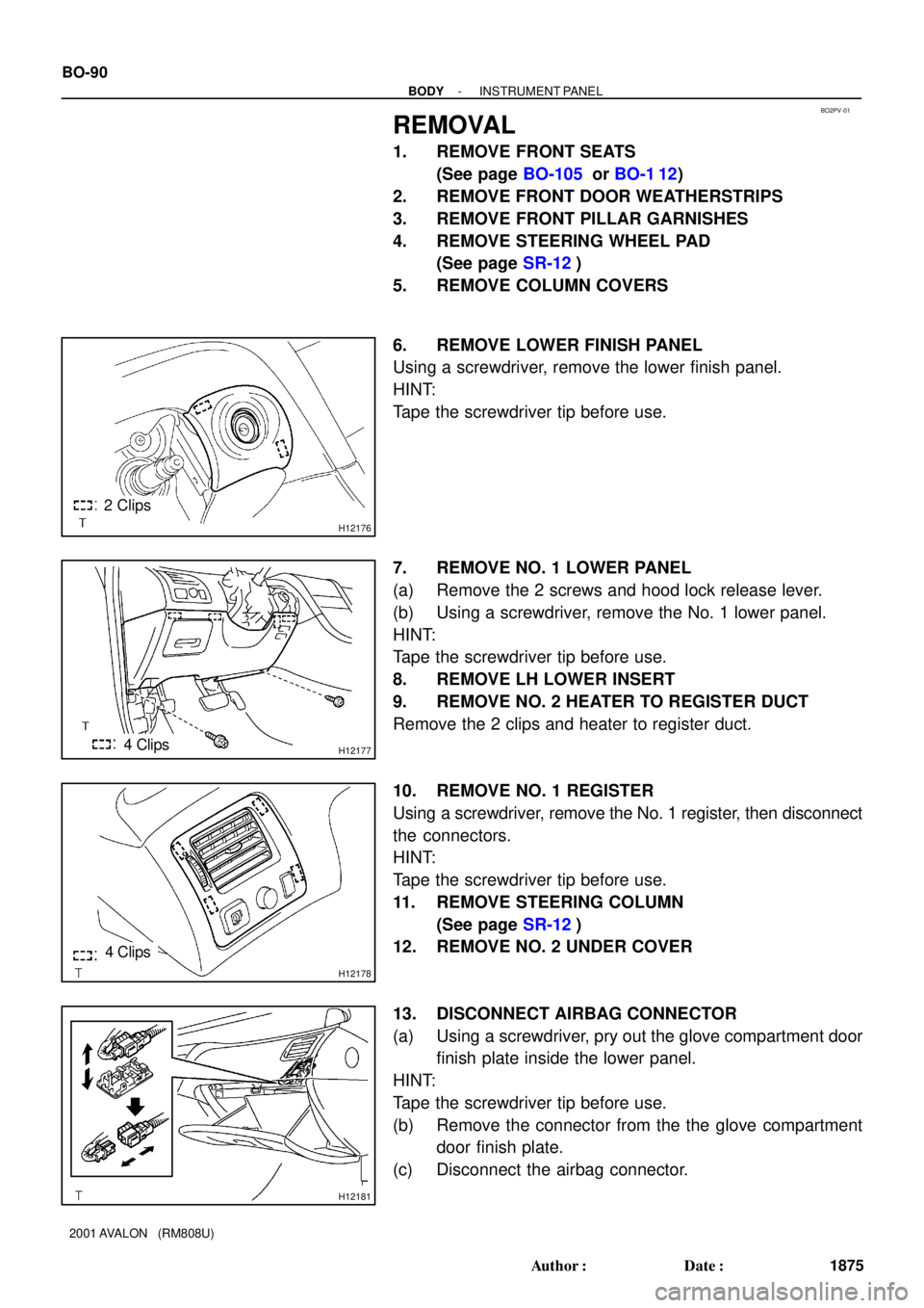
REMOVAL
1. REMOVE FRONT SEATS
(See page BO-105 or BO-1 12)
2. REMOVE FRONT DOOR WEATHERSTRIPS
3. REMOVE FRONT PILLAR GARNISHES
4. REMOVE STEERING WHEEL PAD
(See page SR-12)
5. REMOVE COLUMN COVERS
6. REMOVE LOWER FINISH PANEL
Using a screwdriver, remove the lower finish panel.
HINT:
Tape the screwdriver tip before use.
7. REMOVE NO. 1 LOWER PANEL
(a) Remove the 2 screws and hood lock release lever.
(b) Using a screwdriver, remove the No. 1 lower panel.
HINT:
Tape the screwdriver tip before use.
8. REMOVE LH LOWER INSERT
9. REMOVE NO. 2 HEATER TO REGISTER DUCT
Remove the 2 clips and heater to register duct.
10. REMOVE NO. 1 REGISTER
Using a screwdriver, remove the No. 1 register, then disconnect
the connectors.
HINT:
Tape the screwdriver tip before use.
11. REMOVE STEERING COLUMN
(See page SR-12)
12. REMOVE NO. 2 UNDER COVER
13. DISCONNECT AIRBAG CONNECTOR
(a) Using a screwdriver, pry out the glove compartment door
finish plate inside the lower panel.
HINT:
Tape the screwdriver tip before use.
(b) Remove the connector from the the glove compartment
door finish plate.
(c) Disconnect the airbag connector.
Page 523 of 1897
BR0LV-03
R00327
F09739
BR-60
- BRAKEFRONT SPEED SENSOR
1459 Author�: Date�:
2001 AVALON (RM808U)
REMOVAL
1. DISCONNECT SPEED SENSOR CONNECTOR
(a) Remove the fender liner.
(b) Disconnect the speed sensor connector.
2. REMOVE SPEED SENSOR
(a) Remove the 2 clamp bolts holding the sensor harness to
the body and shock absorber.
Torque: 5.4 N´m (55 kgf´cm, 48 in.´lbf)
(b) Remove the bolt and speed sensor from the steering
knuckle.
Torque: 8.0 N´m (82 kgf´cm, 71 in.´lbf)