Page 720 of 1897

- DIAGNOSTICSABS WITH EBD & BA & TRAC & VSC SYSTEM
DI-259
415 Author�: Date�:
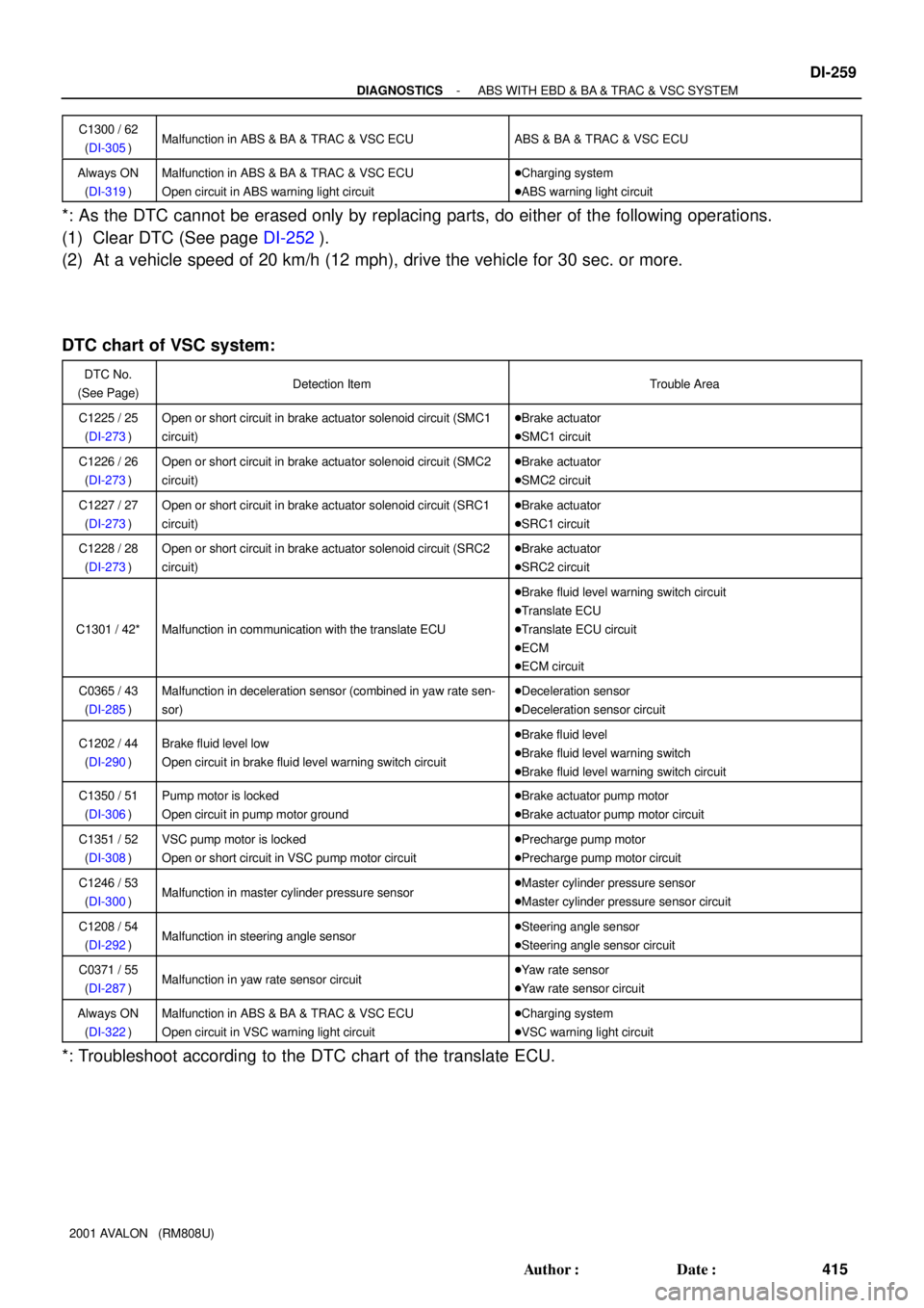
2001 AVALON (RM808U)C1300 / 62
(DI-305)
Malfunction in ABS & BA & TRAC & VSC ECUABS & BA & TRAC & VSC ECU
Always ON
(DI-319)Malfunction in ABS & BA & TRAC & VSC ECU
Open circuit in ABS warning light circuit�Charging system
�ABS warning light circuit
*: As the DTC cannot be erased only by replacing parts, do either of the following operations.
(1) Clear DTC (See page DI-252).
(2) At a vehicle speed of 20 km/h (12 mph), drive the vehicle for 30 sec. or more.
DTC chart of VSC system:
DTC No.
(See Page)Detection ItemTrouble Area
C1225 / 25
(DI-273)Open or short circuit in brake actuator solenoid circuit (SMC1
circuit)�Brake actuator
�SMC1 circuit
C1226 / 26
(DI-273)Open or short circuit in brake actuator solenoid circuit (SMC2
circuit)�Brake actuator
�SMC2 circuit
C1227 / 27
(DI-273)Open or short circuit in brake actuator solenoid circuit (SRC1
circuit)�Brake actuator
�SRC1 circuit
C1228 / 28
(DI-273)Open or short circuit in brake actuator solenoid circuit (SRC2
circuit)�Brake actuator
�SRC2 circuit
C1301 / 42*Malfunction in communication with the translate ECU
�Brake fluid level warning switch circuit
�Translate ECU
�Translate ECU circuit
�ECM
�ECM circuit
C0365 / 43
(DI-285)Malfunction in deceleration sensor (combined in yaw rate sen-
sor)�Deceleration sensor
�Deceleration sensor circuit
C1202 / 44
(DI-290)Brake fluid level low
Open circuit in brake fluid level warning switch circuit�Brake fluid level
�Brake fluid level warning switch
�Brake fluid level warning switch circuit
C1350 / 51
(DI-306)Pump motor is locked
Open circuit in pump motor ground�Brake actuator pump motor
�Brake actuator pump motor circuit
C1351 / 52
(DI-308)VSC pump motor is locked
Open or short circuit in VSC pump motor circuit�Precharge pump motor
�Precharge pump motor circuit
C1246 / 53
(DI-300)Malfunction in master cylinder pressure sensor�Master cylinder pressure sensor
�Master cylinder pressure sensor circuit
C1208 / 54
(DI-292)Malfunction in steering angle sensor�Steering angle sensor
�Steering angle sensor circuit
C0371 / 55
(DI-287)Malfunction in yaw rate sensor circuit�Yaw rate sensor
�Yaw rate sensor circuit
Always ON
(DI-322)Malfunction in ABS & BA & TRAC & VSC ECU
Open circuit in VSC warning light circuit�Charging system
�VSC warning light circuit
*: Troubleshoot according to the DTC chart of the translate ECU.
Page 721 of 1897

DI-260
- DIAGNOSTICSABS WITH EBD & BA & TRAC & VSC SYSTEM
416 Author�: Date�:
2001 AVALON (RM808U)
DTC chart of translate ECU(output NG code DTC of VSC system C1301/42 only):
DTC No.
(See Page)Detection ItemTrouble Area
Normal code*
(DI-317)Malfunction in ECM control system
�ECM circuit
�ECM
�Brake fluid level
�Brake fluid level warning switch circuit
�Steering angle sensor
�ABS & BA & TRAC & VSC ECU
42
(DI-31 1)Malfunction in communication with the ABS & BA & TRAC &
VSC ECU�VSC+ or VSC- circuit
�Translate ECU
�ABS & BA & TRAC & VSC ECU
44
(DI-313)Open or short circuit in NEO circuit
�NEO circuit
�ECM
�Translate ECU
53
(DI-315)Malfunction in communication with the ECM
�TRC+ or TRC- circuit
�ENG+ or ENG- circuit
�ECM
�Translate ECU
Non code
(DI-318)Malfunction in translate ECU
�Tc terminal circuit
�BRAKE warning light circuit
�Translate ECU
*: Translate ECU is normal.
HINT:
The BRAKE warning light does not turn on due to an error in VSC.
If it is on, check that the parking brake pedal is released, the brake fluid level is normal and no malfunction
is identified in the fluid level warning switch system.
Page 723 of 1897
DI6NU-01
F07883
ABS Warning Light
VSC Warning Light
VSC OFF Indicator Light
SLIP Indicator Light
BRAKE Warning Light
DLC2Rear Speed Sensor
Sensor Rotor
Brake Actuator
ABS & BA & TRAC & VSC ECU
VSC OFF Switch Front Speed Sensor
DLC1
ABS Solenoid RelayABS Motor Relay
Room R/B No. 8 Engine
Precharge PumpMaster Cylinder
Pressure Sensor
Parking Brake Switch
Stop Light Switch
Translate ECU
Front Speed Sensor
Sensor Rotor
Sensor Rotor
Rear Speed Sensor
DLC3
Steering Angle Sensor
Yaw Rate Sensor
(Including Deceleration Sensor)
Active Lamp Relay
- DIAGNOSTICSABS WITH EBD & BA & TRAC & VSC SYSTEM
DI-261
417 Author�: Date�:
2001 AVALON (RM808U)
PARTS LOCATION
Page 727 of 1897

F02201
DLC1
TsTc E
1
BR3904
0.13 sec. 0.13 sec.
ON
OFF
BR3893
Malfunction Code (Example Code 72, 76)
72 67
ON
OFF
0.5 sec. 0.5 sec. 0.5 sec. 0.5 sec.1.5 sec.
2.5 sec.4 sec.
Repeat
- DIAGNOSTICSABS WITH EBD & BA & TRAC & VSC SYSTEM
DI-255
411 Author�: Date�:
2001 AVALON (RM808U)
2. SPEED SENSOR SIGNAL CHECK (TEST MODE)
(a) In case of not using TOYOTA hand-held tester:
Check the sensor signal.
(1) Turn the ignition switch OFF.
(2) Using SST, connect terminals Ts and E
1 of DLC1.
SST 09843-18020
(3) Start the engine.
(4) Check that the ABS warning light blinks.
HINT:
If the ABS warning light does not blink, inspect the ABS warning
light circuit (See page DI-325).
(5) Drive vehicle straight forward.
Drive vehicle at a speed faster than 45 km/h (28
mph) for several seconds.
HINT:
The sensor check may not be completed if the front wheels are
spun or the steering wheel is steered during this check.
(6) Stop the vehicle.
(7) Using SST, connect terminals Tc and E
1 of DLC1.
SST 09843-18020
(8) Read the number of blinks of the ABS warning light.
HINT:
�See the list of DTC shown on the next page.
�If every sensor is normal, a normal code is output (A cycle
of 0.25 sec. ON and 0.25 sec. OFF is repeated).
�If 2 or more malfunction codes are identified at the same
time, the lowest numbered code will be displayed 1st.
(9) After doing the check, disconnect the SST from ter-
minals Ts and E
1, Tc and E1 of DLC1, and turn the
ignition switch OFF.
SST 09843-18020
Page 728 of 1897

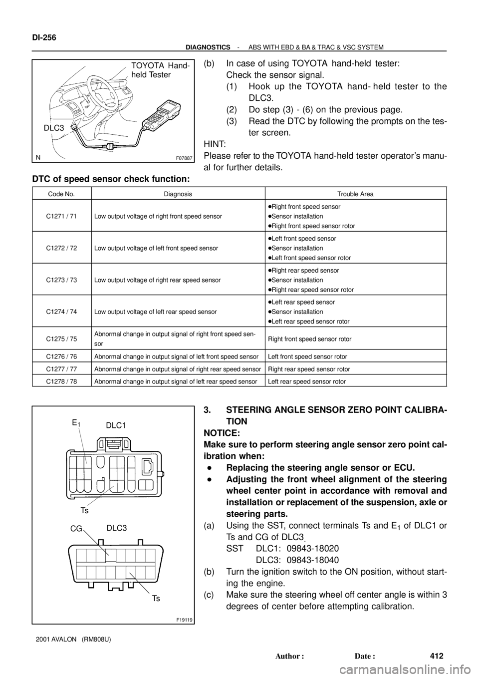
F07887
TOYOTA Hand-
held Tester
DLC3
F19119
DLC1
Ts E1
DLC3
CG
Ts
DI-256
- DIAGNOSTICSABS WITH EBD & BA & TRAC & VSC SYSTEM
412 Author�: Date�:
2001 AVALON (RM808U)
(b) In case of using TOYOTA hand-held tester:
Check the sensor signal.
(1) Hook up the TOYOTA hand- held tester to the
DLC3.
(2) Do step (3) - (6) on the previous page.
(3) Read the DTC by following the prompts on the tes-
ter screen.
HINT:
Please refer to the TOYOTA hand-held tester operator's manu-
al for further details.
DTC of speed sensor check function:
Code No.DiagnosisTrouble Area
C1271 / 71Low output voltage of right front speed sensor
�Right front speed sensor
�Sensor installation
�Right front speed sensor rotor
C1272 / 72Low output voltage of left front speed sensor
�Left front speed sensor
�Sensor installation
�Left front speed sensor rotor
C1273 / 73Low output voltage of right rear speed sensor
�Right rear speed sensor
�Sensor installation
�Right rear speed sensor rotor
C1274 / 74Low output voltage of left rear speed sensor
�Left rear speed sensor
�Sensor installation
�Left rear speed sensor rotor
C1275 / 75Abnormal change in output signal of right front speed sen-
sorRight front speed sensor rotor
C1276 / 76Abnormal change in output signal of left front speed sensorLeft front speed sensor rotor
C1277 / 77Abnormal change in output signal of right rear speed sensorRight rear speed sensor rotor
C1278 / 78Abnormal change in output signal of left rear speed sensorLeft rear speed sensor rotor
3. STEERING ANGLE SENSOR ZERO POINT CALIBRA-
TION
NOTICE:
Make sure to perform steering angle sensor zero point cal-
ibration when:
�Replacing the steering angle sensor or ECU.
�Adjusting the front wheel alignment of the steering
wheel center point in accordance with removal and
installation or replacement of the suspension, axle or
steering parts.
(a) Using the SST, connect terminals Ts and E
1 of DLC1 or
Ts and CG of DLC3
.
SST DLC1: 09843-18020
DLC3: 09843-18040
(b) Turn the ignition switch to the ON position, without start-
ing the engine.
(c) Make sure the steering wheel off center angle is within 3
degrees of center before attempting calibration.
Page 729 of 1897

F09479
IGAGND
Lean to LeftLean to Right GL1
Front
- DIAGNOSTICSABS WITH EBD & BA & TRAC & VSC SYSTEM
DI-257
413 Author�: Date�:
2001 AVALON (RM808U)
HINT:
If the off center angle is greater than 3 degrees from center, fur-
ther adjustments to the tie rods may be necessary.
(d) Shift the gear selector switch to the P range.
(e) Press the VSC OFF switch and hold it while depressing
the brake pedal 3 times within 2 seconds.
(f) Continue to hold the VSC OFF switch until the VSC buzz-
er (repeated beeping) sounds.
(g) Release the VSC OFF switch. The VSC buzzer will con-
tinue to sound for 3 seconds confirming the operation is
complete.
HINT:
If the procedure is done correctly and VSC buzzer does not
sound, there may be a malfunction of the steering angle sensor.
4. DECELERATION SENSOR CHECK
(a) Apply battery positive voltage.
(b) Connect IGA terminal to the battery positive (+) terminal,
and GND terminal to the battery negative (-) terminal, and
apply about 12 V between IGA and GND terminals.
(c) Check the output voltage of GL1 terminal.
SymbolsConditionStandard Value
GL1HorizontalAbout 2.5 V
GL1Lean right downAbout 2.3 V - 4V
GL1Lean left down1 V - About 2.3 V
HINT:
�If the sensor is tilted too much, it may show the wrong val-
ue.
�If dropped, the sensor should be replaced with a new one.
�The sensor removed from the vehicle should not be
placed upside down.
Page 859 of 1897
I11618
32
DI-574
- DIAGNOSTICSCRUISE CONTROL SYSTEM
730 Author�: Date�:
2001 AVALON (RM808U)
3 Check control switch.
PREPARATION:
(a) Remove steering wheel center pad.
(b) Disconnect the control switch connector.
CHECK:
Measure resistance between terminals 2 and 3 of control switch
connector when control switch is operated.
Switch positionResistance (W)
Neutral8 (No continuity)
MAIN0 W (Continuity)
RES/ACC240
SET/COAST630
NG Replace control switch.
OK
4Check harness and connector between cruise control ECU and cruise control switch,
cruise control switch and body ground (See page IN-30).
NG Repair or replace harness or connector.
OK
5 Input signal check (See step 1).
OK Wait and see.
NG
Check and replace cruise control ECU (See
page IN-30).
Page 865 of 1897
N16045
3
4
- DIAGNOSTICSCRUISE CONTROL SYSTEM
DI-591
747 Author�: Date�:
2001 AVALON (RM808U)
2 Check cancel switch continuity.
PREPARATION:
(a) Remove steering wheel center pad (See page SR-12).
(b) Disconnect the control switch connector.
CHECK:
Check continuity between terminals 3 and 4 of control switch
connector when cancel switch is held ON and OFF.
OK:
Switch positionTester connectionSpecified condition
OFF3 - 4No continuity
Hold ON3 - 4Continuity
NG Replace control switch.
OK
3 Check harness and connector between cruise control ECU and cancel switch
(See page IN-30).
NG Repair or replace harness or connector.
OK
Check and replace cruise control ECU (See
page IN-30).