Page 107 of 1897
AX0KB-01
D07772
Radio Assembly with Heater Control & Accessory Assembly Except Taiwan Spec.:
Lower Instrument Panel
Sub-assembly
Lower No. 4 Instrument
Panel Sub-assembly
Hood Lock
Release Lever
Radio Tuner Opening
Covers with Heater
Console & Accessory
Assembly Taiwan Spec.:Taiwan Spec.:
Center Instrument Cluster Finish Panel
Sub-assemblyNo. 2 Instrument Panel
Under Cover Sub-assembly
Front Ash Receptacle Assembly
Upper Console Panel
Sub-assembly
Console Box Plate
Front Console Box
Assembly
Upper Rear Console
Panel Sub-assembly
Clip
Shift Control
Cable
Floor Shift Lever Assembly
12 (120,9)
Rear Console Box Assembly
RH Cowl Side Trim
RH Scuff Plate
N´m (kgf´cm, ft´lbf) : Specified torqueRH Cowl Side Trim
RH Scuff Plate
AX-20
- AUTOMATIC TRANSAXLEFLOOR SHIFT ASSEMBLY
1310 Author�: Date�:
2001 AVALON (RM808U)
FLOOR SHIFT ASSEMBLY
COMPONENTS
Page 120 of 1897
AX0KB-01
D07772
Radio Assembly with Heater Control & Accessory Assembly Except Taiwan Spec.:
Lower Instrument Panel
Sub-assembly
Lower No. 4 Instrument
Panel Sub-assembly
Hood Lock
Release Lever
Radio Tuner Opening
Covers with Heater
Console & Accessory
Assembly Taiwan Spec.:Taiwan Spec.:
Center Instrument Cluster Finish Panel
Sub-assemblyNo. 2 Instrument Panel
Under Cover Sub-assembly
Front Ash Receptacle Assembly
Upper Console Panel
Sub-assembly
Console Box Plate
Front Console Box
Assembly
Upper Rear Console
Panel Sub-assembly
Clip
Shift Control
Cable
Floor Shift Lever Assembly
12 (120,9)
Rear Console Box Assembly
RH Cowl Side Trim
RH Scuff Plate
N´m (kgf´cm, ft´lbf) : Specified torqueRH Cowl Side Trim
RH Scuff Plate
AX-20
- AUTOMATIC TRANSAXLEFLOOR SHIFT ASSEMBLY
1310 Author�: Date�:
2001 AVALON (RM808U)
FLOOR SHIFT ASSEMBLY
COMPONENTS
Page 377 of 1897

BO2PU-02
H12194: Specified torqueN´m (kgf´cm, ft´lbf)
AA
KK
K
K
K
K
K
K
B
L
E
G
GG
G
GG
G
GGI
C
C
C
C
K
K
KKB Instrument Panel Reinforcement
No. 2 Instrument
Panel to Cowl BraceFront Pillar Garnish
Upper Cluster Finish Panel
Instrument Panel
Safety Pad Front Pillar GarnishNo. 1 Heater to
Register Duct
Instrument Panel
to Cowl BraceSpeaker Opening
Cover Assembly
H
H
H
H
H
H
III
G
D EDD
Steering Wheel
Floor shift:
Rear Console Box Floor shift:
Front Console Box
Combination Switch No. 1 Lower PanelLH Lower Insert
Column shift:
Finish Panel Hood Lock
Release LeverNo. 2 Under Cover
Floor shift:
Console Box
Plate
Steering Wheel Pad Steering Column
Cover
Floor shift:
Front Ash Receptacle
Floor shift:
Upper Console PanelLower Finish
Panel Column shift:
Lower Cover LH Register
TAIWAN:
Center Cluster
Finish Panel
TAIWAN:
Opening Covers with
Heater Control Assembly Radio Assembly with Heater
Control AssemblyLower Panel
Cluster Finish Panel
End Finish Panel Combination Meter Lower Cluster
Finish PanelGlove Compartment
Door Finish Plate
Speaker Opening
Cover Assembly
No. 2 Heater to
Register Duct
No. 1 Register
Floor shift:
Cup Holder
Multi Information
Display
Floor shift:
Under Rear
Console Panel
I
HH
50 (510, 37)
20 (204, 15)
N
JJJJConsole Box Hole Cover
Column shift:
Front Ash Receptacle
- BODYINSTRUMENT PANEL
BO-87
1872 Author�: Date�:
2001 AVALON (RM808U)
INSTRUMENT PANEL
COMPONENTS
Page 383 of 1897

BO2PV-01
H12176
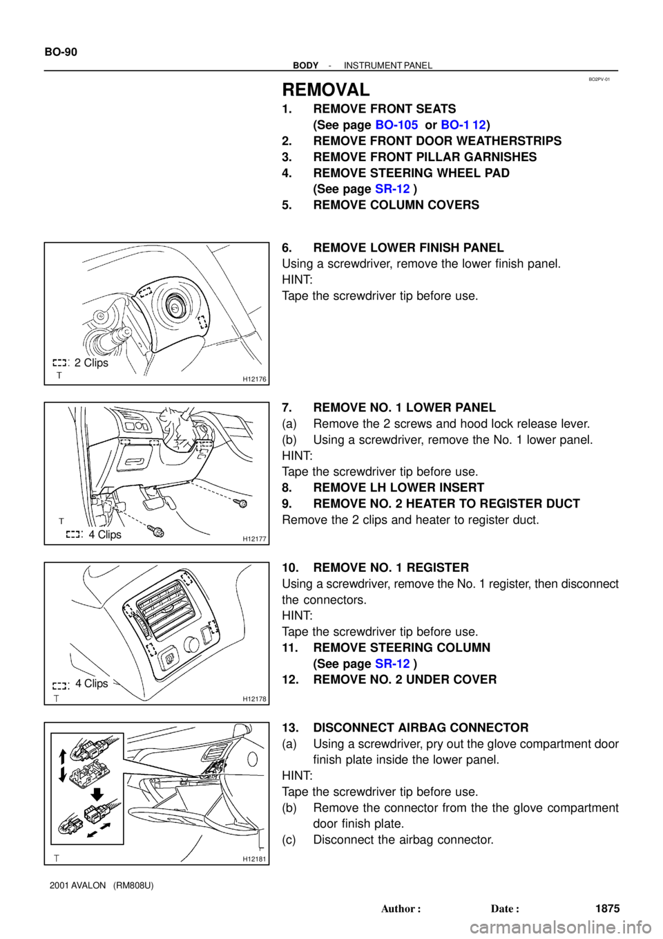
2 Clips
H121774 Clips
H12178
4 Clips
H12181
BO-90
- BODYINSTRUMENT PANEL
1875 Author�: Date�:
2001 AVALON (RM808U)
REMOVAL
1. REMOVE FRONT SEATS
(See page BO-105 or BO-1 12)
2. REMOVE FRONT DOOR WEATHERSTRIPS
3. REMOVE FRONT PILLAR GARNISHES
4. REMOVE STEERING WHEEL PAD
(See page SR-12)
5. REMOVE COLUMN COVERS
6. REMOVE LOWER FINISH PANEL
Using a screwdriver, remove the lower finish panel.
HINT:
Tape the screwdriver tip before use.
7. REMOVE NO. 1 LOWER PANEL
(a) Remove the 2 screws and hood lock release lever.
(b) Using a screwdriver, remove the No. 1 lower panel.
HINT:
Tape the screwdriver tip before use.
8. REMOVE LH LOWER INSERT
9. REMOVE NO. 2 HEATER TO REGISTER DUCT
Remove the 2 clips and heater to register duct.
10. REMOVE NO. 1 REGISTER
Using a screwdriver, remove the No. 1 register, then disconnect
the connectors.
HINT:
Tape the screwdriver tip before use.
11. REMOVE STEERING COLUMN
(See page SR-12)
12. REMOVE NO. 2 UNDER COVER
13. DISCONNECT AIRBAG CONNECTOR
(a) Using a screwdriver, pry out the glove compartment door
finish plate inside the lower panel.
HINT:
Tape the screwdriver tip before use.
(b) Remove the connector from the the glove compartment
door finish plate.
(c) Disconnect the airbag connector.
Page 388 of 1897

BO2PU-02
H12194: Specified torqueN´m (kgf´cm, ft´lbf)
AA
KK
K
K
K
K
K
K
B
L
E
G
GG
G
GG
G
GGI
C
C
C
C
K
K
KKB Instrument Panel Reinforcement
No. 2 Instrument
Panel to Cowl BraceFront Pillar Garnish
Upper Cluster Finish Panel
Instrument Panel
Safety Pad Front Pillar GarnishNo. 1 Heater to
Register Duct
Instrument Panel
to Cowl BraceSpeaker Opening
Cover Assembly
H
H
H
H
H
H
III
G
D EDD
Steering Wheel
Floor shift:
Rear Console Box Floor shift:
Front Console Box
Combination Switch No. 1 Lower PanelLH Lower Insert
Column shift:
Finish Panel Hood Lock
Release LeverNo. 2 Under Cover
Floor shift:
Console Box
Plate
Steering Wheel Pad Steering Column
Cover
Floor shift:
Front Ash Receptacle
Floor shift:
Upper Console PanelLower Finish
Panel Column shift:
Lower Cover LH Register
TAIWAN:
Center Cluster
Finish Panel
TAIWAN:
Opening Covers with
Heater Control Assembly Radio Assembly with Heater
Control AssemblyLower Panel
Cluster Finish Panel
End Finish Panel Combination Meter Lower Cluster
Finish PanelGlove Compartment
Door Finish Plate
Speaker Opening
Cover Assembly
No. 2 Heater to
Register Duct
No. 1 Register
Floor shift:
Cup Holder
Multi Information
Display
Floor shift:
Under Rear
Console Panel
I
HH
50 (510, 37)
20 (204, 15)
N
JJJJConsole Box Hole Cover
Column shift:
Front Ash Receptacle
- BODYINSTRUMENT PANEL
BO-87
1872 Author�: Date�:
2001 AVALON (RM808U)
INSTRUMENT PANEL
COMPONENTS
Page 394 of 1897

BO2PV-01
H12176
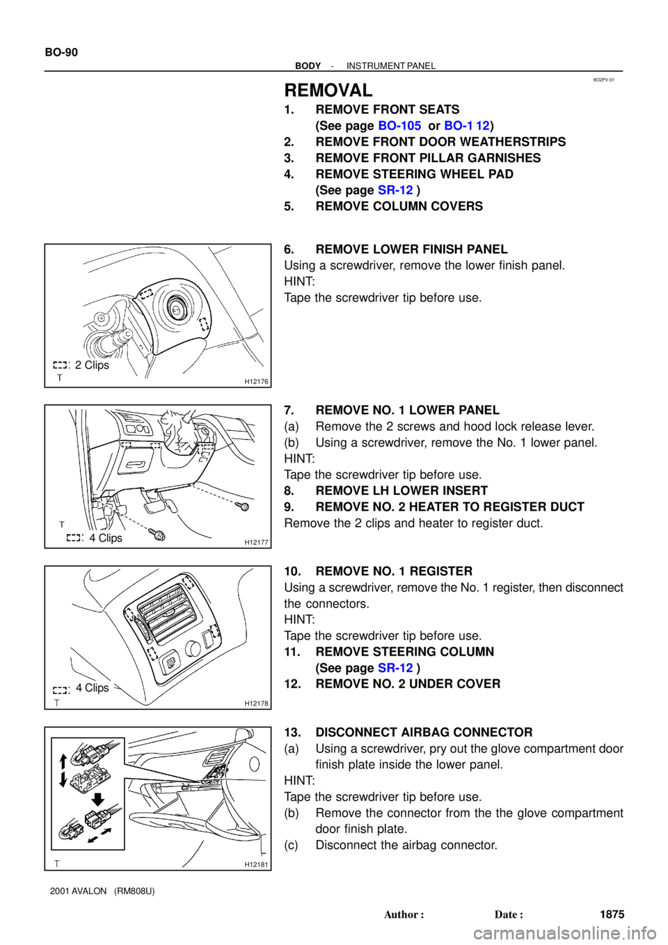
2 Clips
H121774 Clips
H12178
4 Clips
H12181
BO-90
- BODYINSTRUMENT PANEL
1875 Author�: Date�:
2001 AVALON (RM808U)
REMOVAL
1. REMOVE FRONT SEATS
(See page BO-105 or BO-1 12)
2. REMOVE FRONT DOOR WEATHERSTRIPS
3. REMOVE FRONT PILLAR GARNISHES
4. REMOVE STEERING WHEEL PAD
(See page SR-12)
5. REMOVE COLUMN COVERS
6. REMOVE LOWER FINISH PANEL
Using a screwdriver, remove the lower finish panel.
HINT:
Tape the screwdriver tip before use.
7. REMOVE NO. 1 LOWER PANEL
(a) Remove the 2 screws and hood lock release lever.
(b) Using a screwdriver, remove the No. 1 lower panel.
HINT:
Tape the screwdriver tip before use.
8. REMOVE LH LOWER INSERT
9. REMOVE NO. 2 HEATER TO REGISTER DUCT
Remove the 2 clips and heater to register duct.
10. REMOVE NO. 1 REGISTER
Using a screwdriver, remove the No. 1 register, then disconnect
the connectors.
HINT:
Tape the screwdriver tip before use.
11. REMOVE STEERING COLUMN
(See page SR-12)
12. REMOVE NO. 2 UNDER COVER
13. DISCONNECT AIRBAG CONNECTOR
(a) Using a screwdriver, pry out the glove compartment door
finish plate inside the lower panel.
HINT:
Tape the screwdriver tip before use.
(b) Remove the connector from the the glove compartment
door finish plate.
(c) Disconnect the airbag connector.
Page 1474 of 1897

MA001-12
- MAINTENANCEOUTSIDE VEHICLE
MA-1
43 Author�: Date�:
2001 AVALON (RM808U)
OUTSIDE VEHICLE
GENERAL MAINTENANCE
These are maintenance and inspection items which are considered to be the owner's responsibility.
They can be done by the owner or they can have them done at a service shop.
These items include those which should be checked on a daily basis, those which, in most cases, do not
require (special) tools and those which are considered to be reasonable for the owner to do.
Items and procedures for general maintenance are as follows.
1. GENERAL NOTES
�Maintenance items may vary from country to country. Check the owner's manual supplement in which
the maintenance schedule is shown.
�Every service item in the periodic maintenance schedule must be performed.
�Periodic maintenance service must be performed according to whichever interval in the periodic main-
tenance schedule occurs first, the odometer reading (miles) or the time interval (months).
�Maintenance service after the last period should be performed at the same interval as before unless
otherwise noted.
�Failure to do even one item an cause the engine to run poorly and increase exhaust emissions.
2. TIRES
(a) Check the pressure with a gauge. If necessary, adjust.
(b) Check for cuts, damage or excessive wear.
3. WHEEL NUTS
When checking the tires, check the nuts for looseness or for missing nuts. If necessary, tighten them.
4. TIRE ROTATION
Check the owner's manual supplement in which the maintenance schedule is shown.
5. WINDSHIELD WIPER BLADES
Check for wear or cracks whenever they do not wipe clean. If necessary, replace.
6. FLUID LEAKS
(a) Check underneath for leaking fuel, oil, water or other fluid.
(b) If you smell gasoline fumes or notice any leak, have the cause found and corrected.
7. DOORS AND ENGINE HOOD
(a) Check that all doors including the trunk lid operate smoothly, and that all latches lock securely.
(b) Check that the engine hood secondary latch secures the hood from opening when the primary latch
is released.
Page 1817 of 1897
SR0EH-06
F08837
Floor shift:
8.8 (90, 78 in.´lbf)
50 (510, 37)
Torx ScrewSteering Wheel Pad
Steering Wheel Lower
No. 2 Cover
Combination Switch
(w/ Spiral cable)
Column Upper Cover
Column Lower CoverSteering Wheel Lower
No. 2 CoverSteering Wheel
Steering Column
Assembly
Clamp
Intermediate Shaft
Sub-assembly
25 (260, 19)
N´m (kgf´cm, ft´lbf): Specified torqueTorx Screw
Lower Instrument Finish
Panel Assembly
Return Spring
No. 2 Column Hole
Cover Sub-assemblyUniversal Joint Assembly No. 2 Column Lower CoverSteering Angle
Sensor
Lower No. 1 Instrument
Panel Sub-assembly
Lower LH Instrument Panel
Insert Sub-assembly
No. 2 Heater to Register Duct
Air Cleaner Assembly
with Air Cleaner Hose
Steering Angle
Sensor Adapter Speed Control Main
Switch Assemblyw/ VSC:
w/ VSC:
8.8 (90, 78 in.´lbf)
35 (360, 26)
35 (360, 26)
35 (360, 26)
Hood Lock Release Lever
- STEERINGTILT STEERING COLUMN
SR-9
1472
2001 AVALON (RM808U)
TILT STEERING COLUMN
COMPONENTS