Page 97 of 1897
AT3412
AX03Z-05
AX-42
- AUTOMATIC TRANSAXLEAUTOMATIC TRANSAXLE UNIT
1332 Author�: Date�:
2001 AVALON (RM808U)
INSTALLATION
1. CHECK TORQUE CONVERTER CLUTCH INSTALLA-
TION
Using a scale and a straight edge, measure the distance from
the installed surface to the transaxle housing.
Correct distance: 13.7 mm (0.539 in.) or more
2. TRANSAXLE INSTALLATION
Installation is in the reverse order of removal (See page
AX-35).
HINT:
After installation, check and inspect the following items.
�Fill ATF and check fluid level (See page DI-160).
�Check front wheel alignment (See page SA-4).
�Do the road test (See page DI-160).
�Adjust the hood (See page BO-6).
NOTICE:
w/ VSC:
After installation, perform the steering angle sensor zero
point calibration (See page DI-252).
Page 106 of 1897
Q00394
SST
AX03S-05
Q06348
SST
Q00238
SST AX-14
- AUTOMATIC TRANSAXLEDIFFERENTIAL OIL SEAL
1304 Author�: Date�:
2001 AVALON (RM808U)
DIFFERENTIAL OIL SEAL
ON-VEHICLE REPAIR
1. REMOVE FRONT DRIVE SHAFT
(See page SA-16)
2. REMOVE SIDE GEAR SHAFT OIL SEAL
Using SST, pull out the oil seal.
SST 09308-00010
3. INSTALL LEFT SIDE GEAR SHAFT OIL SEAL
(a) Using SST and a hammer, drive in a new oil seal.
SST 09223-15020, 09350-32014 (09351-32130)
Oil seal depth: 0 ± 0.5 mm (0 ± 0.02 in.)
(b) Coat the lip of the oil seal with MP grease.
4. INSTALL RIGHT SIDE GEAR SHAFT OIL SEAL
(a) Using SST and a hammer, drive in a new oil seal.
SST 09316-60010 (09316-00010)
Oil seal depth: 0 ± 0.5 mm (0 ± 0.02 in.)
(b) Coat the lip of the oil seal with MP grease.
5. INSTALL FRONT DRIVE SHAFT
(See page SA-24)
6. CHECK TRANSAXLE FLUID LEVEL
(See page DI-160)
Page 134 of 1897
Q06496
- AUTOMATIC TRANSAXLEPARK/NEUTRAL POSITION (PNP) SWITCH
AX-5
1295 Author�: Date�:
2001 AVALON (RM808U)
(f) Install the control cable and nut.
Torque: 15 N´m (150 kgf´cm, 11 ft´lbf)
(g) Install the clip to the shift control cable.
5. CONNECT PARK/NEUTRAL POSITION SWITCH CON-
NECTOR
6. CHECK PARK/NEUTRAL POSITION SWITCH OPERA-
TION
Check that the engine can be started with the shift lever only in
the N or P position, but not in other positions.
If not as started above, carry out the adjustment procedure
(See page DI-160).
7. TEST DRIVE VEHICLE
8. INSTALL ENGINE UNDER COVER
Page 143 of 1897
D07234
Q09982
- AUTOMATIC TRANSAXLETHROTTLE CABLE
AX-13
1303 Author�: Date�:
2001 AVALON (RM808U)
9. CONNECT THROTTLE CABLE TO ENGINE
Torque: 15 N´m (150 kgf´cm, 11 ft´lbf)
10. ADJUST THROTTLE CABLE (See page DI-160)
11. INSTALL PARK/NEUTRAL POSITION SWITCH
(See page AX-4)
12. INSTALL CRUISE CONTROL ACTUATOR
(a) Install the cruise control actuator with the 3 bolts.
Torque: 13 N´m (130 kgf´cm, 9 ft´lbf)
(b) Connect the connector.
13. INSTALL BATTERY
14. TEST DRIVE VEHICLE
Page 149 of 1897
Z19256
BA
B A
AT3741
AT3785
- AUTOMATIC TRANSAXLEVALVE BODY ASSEMBLY
AX-1 1
1301 Author�: Date�:
2001 AVALON (RM808U)
24. INSTALL OIL STRAINER AND APPLY PIPE BRACKET
Install the oil strainer and apply pipe bracket with the 6 bolts.
Torque:
Bolt A: 10 N´m (100 kgf´cm, 7 ft´lbf)
Bolt B: 11 N´m (110 kgf´cm, 8 ft´lbf)
Bolt length:
Bolt A: 22 mm (0.866 in.)
Bolt B: 53 mm (2.087 in.)
25. INSTALL MAGNET IN PLACE
Install the 3 magnets in the indentations of the oil pan, as shown
in the illustration.
NOTICE:
Make sure that the magnet does not interfere with the oil
pipes.
26. INSTALL OIL PAN AND GASKET
(a) Install the oil pan and a new gasket.
(b) Install the 17 bolts.
Torque: 7.8 N´m (80 kgf´cm, 69 in.´lbf)
27. INSTALL DRAIN PLUG
Install a new gasket and drain plug.
Torque: 49 N´m (500 kgf´cm, 36 ft´lbf)
28. FILL ATF AND CHECK FLUID LEVEL
(See page DI-160)
Page 587 of 1897

CO0WT-01
B09040
- COOLINGRADIATOR
CO-17
1210 Author�: Date�:
2001 AVALON (RM808U)
REMOVAL
HINT:
At the time of installation, please refer to the following items.
�Start the engine, and check for coolant and A/T fluid
leaks.
�Check the A/T fluid level (See page DI-160).
1. REMOVE BATTERY AND BATTERY TRAY
2. REMOVE ENGINE UNDER COVER
3. DRAIN ENGINE COOLANT
4. DISCONNECT NO.3 ENGINE ROOM RELAY BLOCK
FROM RADIATOR
5. DISCONNECT NO.1 COOLING FAN CONNECTOR
6. DISCONNECT WIRE CLAMPS FROM NO.1 FAN
SHROUD
7. DISCONNECT NO.2 COOLING FAN CONNECTOR
8. DISCONNECT NO.1 ECT SWITCH WIRE CONNECTOR
9. DISCONNECT WIRE CLAMPS FROM NO.2 FAN
SHROUD
10. DISCONNECT UPPER RADIATOR HOSE FROM RA-
DIATOR
11. DISCONNECT LOWER RADIATOR HOSE FROM RA-
DIATOR
12. DISCONNECT A/T OIL COOLER HOSES FROM RA-
DIATOR
13. REMOVE RADIATOR AND COOLING FANS AS-
SEMBLY
(a) Remove the 2 bolts and 2 upper supports.
Torque: 12.8 N´m (130 kgf´cm, 9 ft´lbf)
(b) Lift out the radiator, and remove the radiator and cooling
fans assembly.
(c) Remove the 2 lower supports.
14. REMOVE NO.1 ECT SWITCH
15. REMOVE NO.1 COOLING FAN FROM RADIATOR
Remove the 2 bolts and cooling fan.
Torque: 5.0 N´m (50 kgf´cm, 44 in.´lbf)
16. REMOVE NO.2 COOLING FAN FROM RADIATOR
Remove the 2 bolts and cooling fan.
Torque: 5.0 N´m (50 kgf´cm, 44 in.´lbf)
Page 769 of 1897

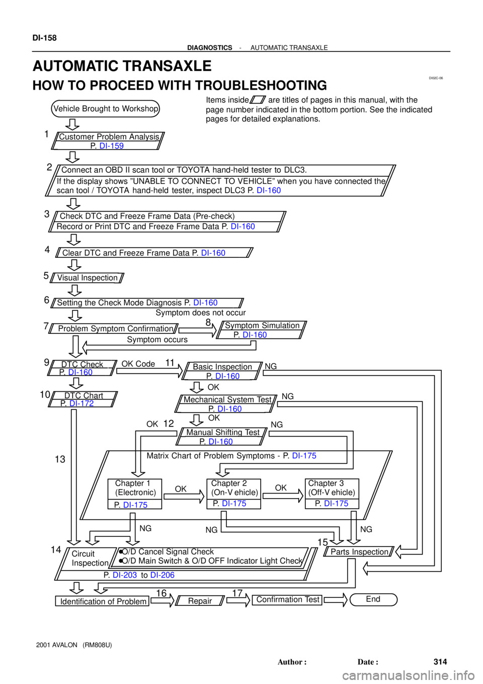
DI02C-06
Mechanical System Test
P. DI-160NG
Customer Problem Analysis Vehicle Brought to Workshop
Check DTC and Freeze Frame Data (Pre-check)Items inside
P. DI-159are titles of pages in this manual, with the
page number indicated in the bottom portion. See the indicated
pages for detailed explanations.
Connect an OBD II scan tool or TOYOTA hand-held tester to DLC3.
If the display shows ºUNABLE TO CONNECT TO VEHICLEº when you have connected the
scan tool / TOYOTA hand-held tester, inspect DLC3 P. DI-160
Record or Print DTC and Freeze Frame Data P. DI-160
Clear DTC and Freeze Frame Data P. DI-160
Symptom does not occur
Problem Symptom Confirmation
P. DI-160 Symptom Simulation
Symptom occurs
P. DI-160 OK Code
DTC Check
P. DI-160
DTC Chart
P. DI-172Basic Inspection
Manual Shifting TestOK
P. DI-160NG
NG
NG NG
NG OKOK
OKOK Matrix Chart of Problem Symptoms - P. DI-175
Chapter 1
(Electronic)Chapter 2
(On-V ehicle)
P. DI-175
P. DI-175Chapter 3
(Off-V ehicle)
P. DI-175
Circuit
Inspection�O/D Cancel Signal Check
�O/D Main Switch & O/D OFF Indicator Light Check
P. DI-203 to DI-206
Identification of ProblemParts Inspection
End
Confirmation Test
Repair Setting the Check Mode Diagnosis P. DI-160 Visual Inspection1
5
9
16 2
6
10
15 3
7
11
14 4
8
12
13
17
DI-158
- DIAGNOSTICSAUTOMATIC TRANSAXLE
314 Author�: Date�:
2001 AVALON (RM808U)
AUTOMATIC TRANSAXLE
HOW TO PROCEED WITH TROUBLESHOOTING
Page 771 of 1897

DI02E-08
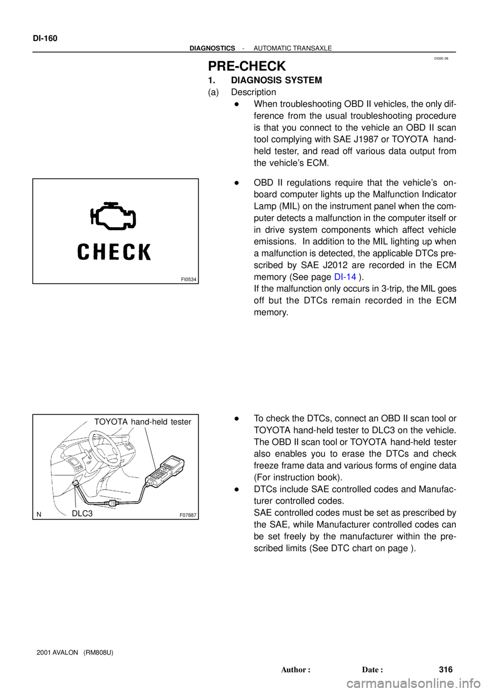
FI0534
F07887DLC3
TOYOTA hand-held tester
DI-160
- DIAGNOSTICSAUTOMATIC TRANSAXLE
316 Author�: Date�:
2001 AVALON (RM808U)
PRE-CHECK
1. DIAGNOSIS SYSTEM
(a) Description
�When troubleshooting OBD II vehicles, the only dif-
ference from the usual troubleshooting procedure
is that you connect to the vehicle an OBD II scan
tool complying with SAE J1987 or TOYOTA hand-
held tester, and read off various data output from
the vehicle's ECM.
�OBD II regulations require that the vehicle's on-
board computer lights up the Malfunction Indicator
Lamp (MIL) on the instrument panel when the com-
puter detects a malfunction in the computer itself or
in drive system components which affect vehicle
emissions. In addition to the MIL lighting up when
a malfunction is detected, the applicable DTCs pre-
scribed by SAE J2012 are recorded in the ECM
memory (See page DI-14).
If the malfunction only occurs in 3-trip, the MIL goes
off but the DTCs remain recorded in the ECM
memory.
�To check the DTCs, connect an OBD II scan tool or
TOYOTA hand-held tester to DLC3 on the vehicle.
The OBD II scan tool or TOYOTA hand-held tester
also enables you to erase the DTCs and check
freeze frame data and various forms of engine data
(For instruction book).
�DTCs include SAE controlled codes and Manufac-
turer controlled codes.
SAE controlled codes must be set as prescribed by
the SAE, while Manufacturer controlled codes can
be set freely by the manufacturer within the pre-
scribed limits (See DTC chart on page ).