Page 1793 of 1897

9. INSTALL OIL SEAL
(a) Coat a new oil seal lip with power steering fl")
W03562
Press
SST
Oil Seal
R11648
SST
R11659
Punch
- STEERINGPOWER STEERING GEAR
SR-51
1514 Author�: Date�:
2001 AVALON (RM808U)
9. INSTALL OIL SEAL
(a) Coat a new oil seal lip with power steering fluid.
(b) Using SST, press in the oil seal.
SST 09612-2201 1
NOTICE:
Make sure that the oil seal is installed facing in the correct
direction.
10. INSTALL CONTROL VALVE HOUSING WITH CON-
TROL VALVE ASSEMBLY
(a) Place a new gasket on the rack housing.
(b) Align the matchmarks on the control valve housing and
rack housing.
(c) Install the 2 bolts.
Torque: 18 N´m (180 kgf´cm, 13 ft´lbf)
11. INSTALL SELF-LOCKING NUT
Using SST, stop the control valve shaft rotating and install a new
self-locking nut.
SST 09616-0001 1
Torque: 25 N´m (250 kgf´cm, 18 ft´lbf)
12. INSTALL DUST SEAL
13. INSTALL RACK HOUSING CAP
(a) Apply sealant to 2 or 3 threads of the rack housing cap.
Sealant:
Part No.08833-00080, THREE BOND 1344,
LOCTITE 242 or equivalent
(b) Install the rack housing cap.
Torque: 59 N´m (600 kgf´cm, 43 ft´lbf)
(c) Using a punch and hammer, stake the 2 parts of the rack
housing cap.
14. INSTALL RACK GUIDE SUB- ASSEMBLY, RACK
GUIDE SPRING AND RACK GUIDE SPRING CAP
(a) Install the rack guide sub- assembly and rack guide
spring.
(b) Apply sealant to 2 or 3 threads of the rack guide spring
cap.
Sealant:
Part No.08833-00080, THREE BOND 1344,
LOCTITE 242 or equivalent
(c) Temporarily install the rack guide spring cap.
Page 1794 of 1897
W03098
SST Rack Guide
Spring Cap
W03099
12°
W03100
SST
W03101
SST
Rack Guide
Spring CapSST SR-52
- STEERINGPOWER STEERING GEAR
1515 Author�: Date�:
2001 AVALON (RM808U)
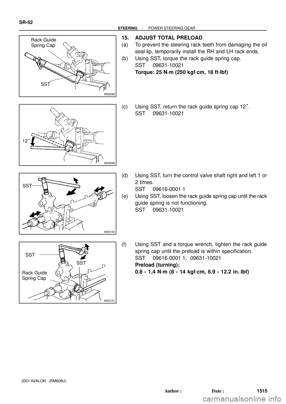
15. ADJUST TOTAL PRELOAD
(a) To prevent the steering rack teeth from damaging the oil
seal lip, temporarily install the RH and LH rack ends.
(b) Using SST, torque the rack guide spring cap.
SST 09631-10021
Torque: 25 N´m (250 kgf´cm, 18 ft´lbf)
(c) Using SST, return the rack guide spring cap 12°.
SST 09631-10021
(d) Using SST, turn the control valve shaft right and left 1 or
2 times.
SST 09616-0001 1
(e) Using SST, loosen the rack guide spring cap until the rack
guide spring is not functioning.
SST 09631-10021
(f) Using SST and a torque wrench, tighten the rack guide
spring cap until the preload is within specification.
SST 09616-0001 1, 09631-10021
Preload (turning):
0.8 - 1.4 N´m (8 - 14 kgf´cm, 6.9 - 12.2 in.´lbf)
Page 1795 of 1897

16. INSTALL RACK GUIDE")
W03102
SSTRack Guide
Spring Cap
Lock Nut
SST Fulcrum
Length
R11667
Claw
F03861
Fulcrum
Length
SST
- STEERINGPOWER STEERING GEAR
SR-53
1516 Author�: Date�:
2001 AVALON (RM808U)
16. INSTALL RACK GUIDE SPRING CAP LOCK NUT
(a) Apply sealant to 2 or 3 threads of the rack guide spring
cap lock nut.
Sealant:
Part No.08833-00080, THREE BOND 1344,
LOCTITE 242 or equivalent
(b) Temporarily install the rack guide spring cap lock nut.
(c) Using SST, hold the rack guide spring cap and using
another SST torque the rack guide spring cap lock nut.
SST 09631-10021, 09922-10010
Torque: 50 N´m (510 kgf´cm, 37 ft´lbf)
NOTICE:
Use SST 09922-10010 in the direction shown in the illustra-
tion.
HINT:
Use a torque wrench with a fulcrum length of 345 mm (13.58
in.).
(d) Recheck the total preload.
Preload (turning):
0.8 - 1.4 N´m (8 - 14 kgf´cm, 6.9 - 12.2 in.´lbf)
(e) Remove the RH and LH rack ends.
17. INSTALL RH AND LH CLAW WASHERS AND RACK
ENDS
(a) Install a new claw washer, and temporarily install the rack
ends.
HINT:
Align the claws of the claw washers with the steering rack
grooves.
(b) Using a spanner (24 mm), hold the steering rack steadily
and using SST, torque the rack end.
SST 09922-10010
Torque: 60 N´m (610 kgf´cm, 44 ft´lbf)
NOTICE:
Use SST 09922-10010 in the direction shown in the illustra-
tion.
HINT:
Use a torque wrench with a fulcrum length of 345 mm (13.58
in.).
Page 1796 of 1897

or less
SST
R00429
Matchmarks SR-54
- STEERINGPOWER STEERING GEAR
1517 Author�: Date�:
2001 AVALON (RM808U)
(c) Using a brass bar and hammer, stake the")
R11668
Brass Bar
R11669
W04223
2 mm
(0.79 in.)
or less
SST
R00429
Matchmarks SR-54
- STEERINGPOWER STEERING GEAR
1517 Author�: Date�:
2001 AVALON (RM808U)
(c) Using a brass bar and hammer, stake the claw washer.
NOTICE:
Avoid any impact on the steering rack.
(d) Employ the same manner described above to the other
side.
18. INSTALL RH AND LH RACK BOOTS, CLAMPS AND
CLIPS
(a) Ensure that the steering rack hole is not clogged with
grease.
HINT:
If the hole is clogged, the pressure inside the rack boot will
change after it is assembled and the steering wheel is turned.
(b) Install the rack boot, clip and a new clamp.
NOTICE:
Be careful not to damage or twist the rack boot.
(c) Using SST, tighten the clamp as shown in the illustration.
SST 09521-24010
(d) Employ the same manner described above to the other
side.
19. INSTALL RH AND LH TIE ROD ENDS AND LOCK NUTS
(a) Screw the lock nut and tie rod end onto the rack end until
the matchmarks are aligned.
(b) After adjusting toe-in, torque the lock nut (See page
SA-4).
Torque: 74 N´m (750 kgf´cm, 54 ft´lbf)
(c) Employ the same manner described above to the other
side.
Page 1797 of 1897
F13588SST
Fulcrum
Length
- STEERINGPOWER STEERING GEAR
SR-55
1518 Author�: Date�:
2001 AVALON (RM808U)
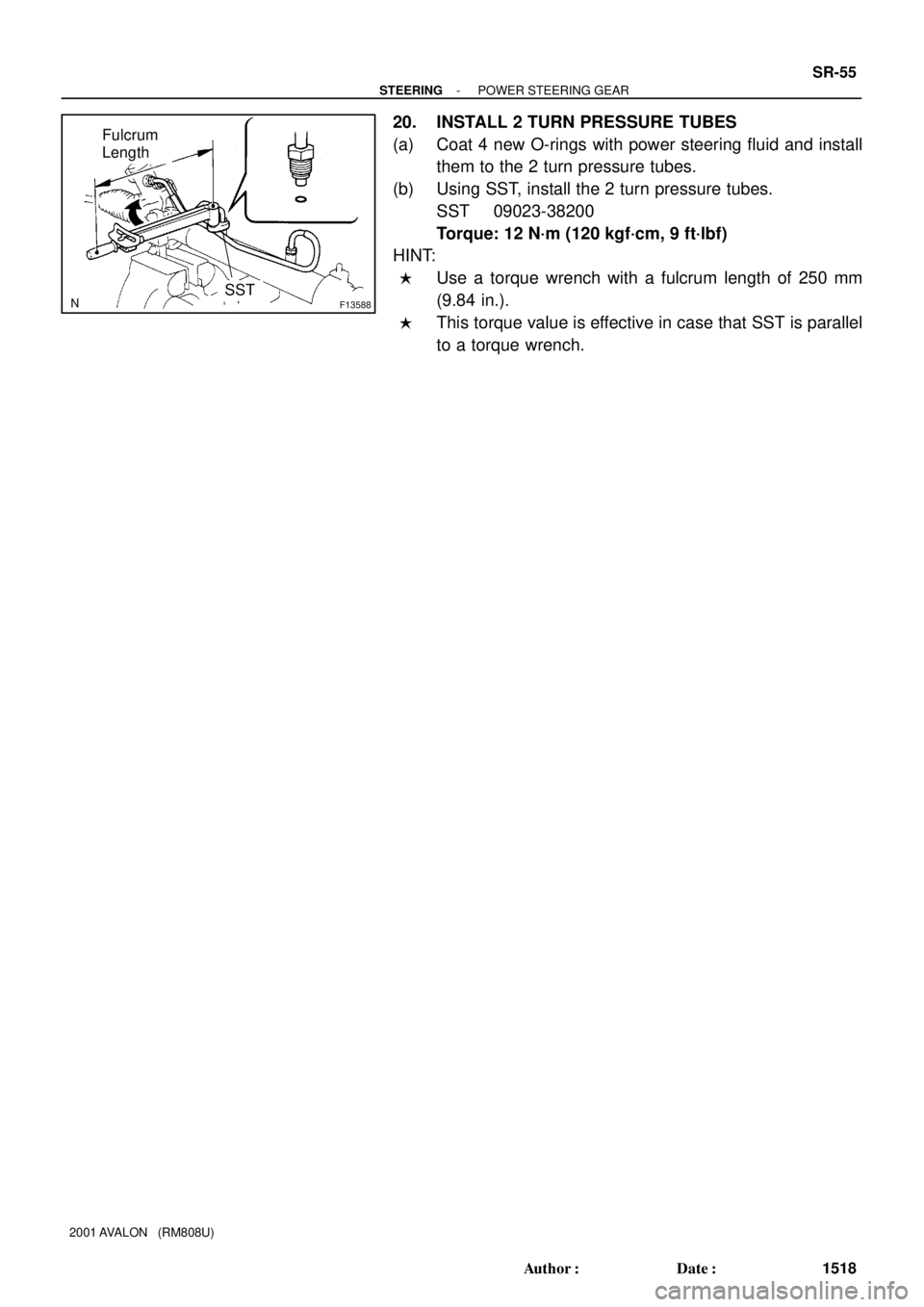
20. INSTALL 2 TURN PRESSURE TUBES
(a) Coat 4 new O-rings with power steering fluid and install
them to the 2 turn pressure tubes.
(b) Using SST, install the 2 turn pressure tubes.
SST 09023-38200
Torque: 12 N´m (120 kgf´cm, 9 ft´lbf)
HINT:
�Use a torque wrench with a fulcrum length of 250 mm
(9.84 in.).
�This torque value is effective in case that SST is parallel
to a torque wrench.
Page 1802 of 1897
SR0EN-06
F08851
Connector
Oil Pressure Switch
Union Bolt
� Gasket
Return HoseDrive Belt
Clamp Plate
Pressure Feed Tube
Pressure Feed Tube
PS Vane Pump AssemblyHolder
Clamp Plate
Clamp Plate
Front Fender Apron Seal RH
� Non-reusable part
43 (440, 32)
*29 (300, 22)
7.8 (80, 69 in.´lbf)
21 (210, 15)
52 (530, 38)
43 (440, 32)
25 (250, 18)
*22 (230, 17)
N´m (kgf´cm, ft´lbf): Specified torque
* For use with SST
- STEERINGPOWER STEERING VANE PUMP
SR-25
1488 Author�: Date�:
2001 AVALON (RM808U)
POWER STEERING VANE PUMP
COMPONENTS
Page 1803 of 1897
F08852
Pressure Port Union
� O-Ring
Flow Control Valve
Suction Port Union
SpringRear Housing
Rear
Bracket
Front Housing
Front Bracket
Vane Pump Shaft
Vane Pump PulleyVane Pump
Rotor
� Straight Pin
Wave Washer � O-Ring� O-Ring
� Gasket
Side Plate
Cam Ring
Vane Platex 10
� Oil Seal�
� Snap Ring
� Non-reusable part
Power steering fluid
83 (850, 62)
13 (130, 9)
43 (440, 32)
43 (440, 32)
17 (170, 12)
17 (170, 12)
44 (450, 33)
N´m (kgf´cm, ft´lbf): Specified torque
SR-26
- STEERINGPOWER STEERING VANE PUMP
1489 Author�: Date�:
2001 AVALON (RM808U)
Page 1804 of 1897

DISASSEMBLY
NOTICE:
When using a vise, do not overtighten it.
1. MEASURE PS VANE PUMP RO")
SR0EP-04
F08853
F08854
SST
SR-28
- STEERINGPOWER STEERING VANE PUMP
1491 Author�: Date�:
2001 AVALON (RM808U)
DISASSEMBLY
NOTICE:
When using a vise, do not overtighten it.
1. MEASURE PS VANE PUMP ROTATING TORQUE
(a) Check that the pump rotates smoothly without abnormal
noise.
(b) Using a torque wrench, check the pump rotating torque.
Rotating torque:
0.3 N´m (2.8 kgf´cm, 2.4 in.´lbf) or less
2. REMOVE VANE PUMP PULLEY
(a) Using SST, stop the pulley rotating and loosen the nut.
(b) Remove the nut and vane pump pulley from the vane
pump shaft.
SST 09960-10010 (09962-01000, 09963-01000)
3. REMOVE FRONT AND REAR BRACKETS
Remove the 3 bolts, 2 nuts, front and rear brackets.
4. REMOVE SUCTION PORT UNION
(a) Remove the bolt and suction port union.
(b) Remove the O-ring from the suction port union.
5. REMOVE PRESSURE PORT UNION, FLOW CONTROL
VALVE AND SPRING
(a) Remove the pressure port union, flow control valve and
spring.
(b) Remove the O-ring from the pressure port union.
6. REMOVE REAR HOUSING
(a) Remove the 4 bolts and rear housing.
(b) Remove the 2 O-rings from the rear housing.
7. REMOVE WAVE WASHER
8. REMOVE SIDE PLATE
9. REMOVE GASKET
10. REMOVE CAM RING, 10 VANE PLATES AND VANE
PUMP ROTOR
(a) Remove the cam ring and 10 vane plates.
NOTICE:
Take care not to drop the plate.
(b) Using a screwdriver, remove the snap ring and vane
pump rotor from the vane pump shaft.
11. REMOVE VANE PUMP SHAFT
12. REMOVE 2 STRAIGHT PINS
Remove the 2 straight pins from the front housing.