Page 95 of 1897
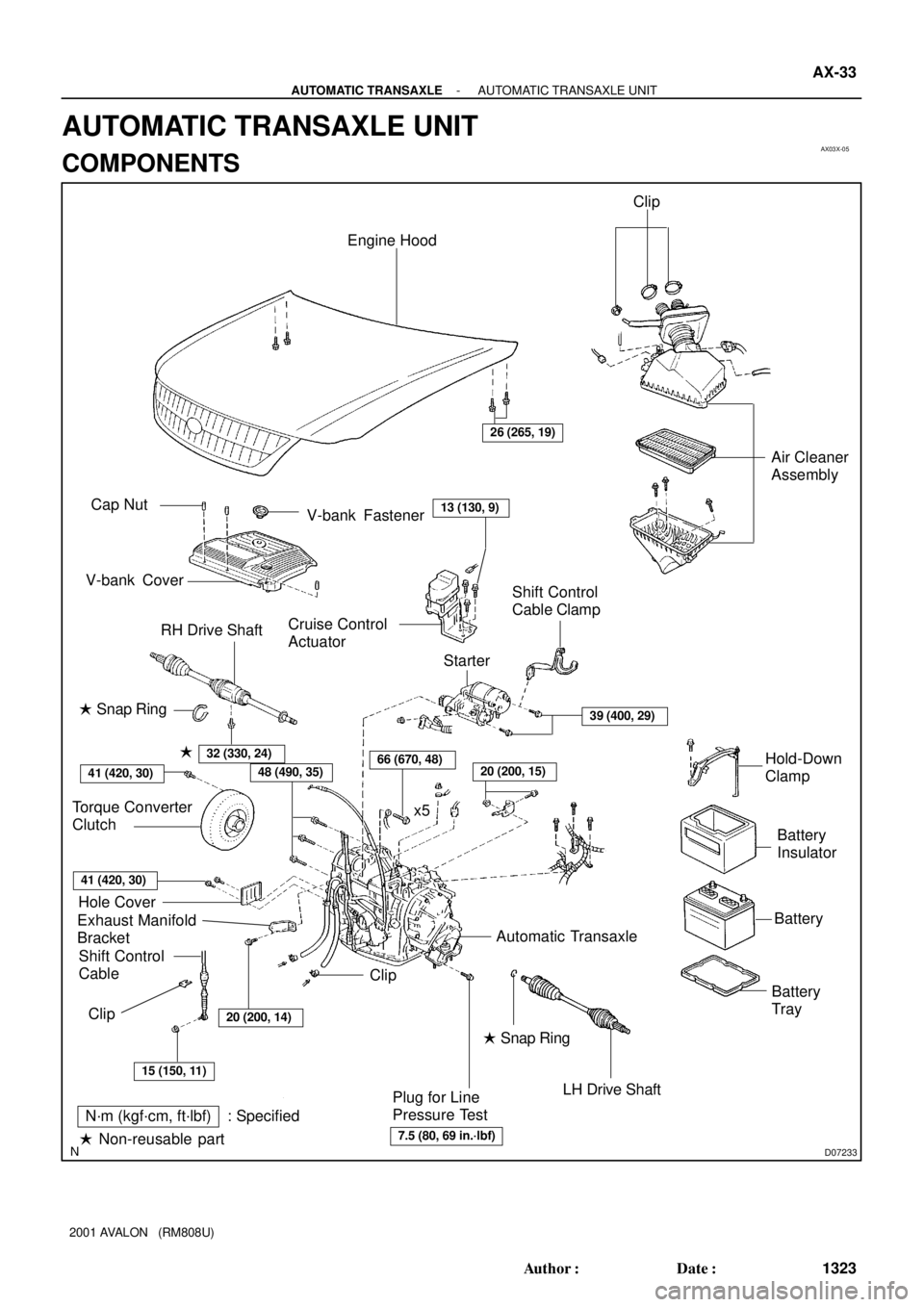
AX03X-05
D07233
Engine Hood
Cruise Control
Actuator RH Drive ShaftAir Cleaner
Assembly
Shift Control
Cable
LH Drive Shaft
Plug for Line
Pressure TestBattery
TrayBatteryBattery
Insulator � Snap Ring
Exhaust Manifold
BracketHole Cover Torque Converter
ClutchShift Control
Cable Clamp
Starter
ClipHold-Down
Clamp
N´m (kgf´cm, ft´lbf) : Specified
� Non-reusable part� Snap Ring �
x5
26 (265, 19)
48 (490, 35)66 (670, 48)20 (200, 15)
15 (150, 11)
7.5 (80, 69 in.´lbf)
Automatic Transaxle
39 (400, 29)
20 (200, 14)
Clip
32 (330, 24)
13 (130, 9)Cap Nut
V-bank CoverV-bank Fastener
41 (420, 30)
41 (420, 30)
Clip
- AUTOMATIC TRANSAXLEAUTOMATIC TRANSAXLE UNIT
AX-33
1323 Author�: Date�:
2001 AVALON (RM808U)
AUTOMATIC TRANSAXLE UNIT
COMPONENTS
Page 96 of 1897
D07770
RH Fender
Apron SealRH Rear
Lower BraceRear Side Engine
Mounting Insulator
PS Reservoir
Pipe
Front Side Engine
Mounting Insulator
RH Front
Lower Brace
LH Front
Lower Brace
Exhaust Front Pipe Support Bracket
RH Fender LinerGrommet
� Gasket
Front Exhaust Pipe
Exhaust Front Pipe
Support Stay
Engine Under CoverCenter Engine
Under CoverLH Fender LinerStabilizer Bar
Stabilizer Bar Link
LH Fender Apron Seal
LH Rear
Lower Brace
Tie Rod End
� Cotter Pin
� Cotter Pin
� Gasket
� Gasket
Spring
N´m (kgf´cm, ft´lbf) : Specified torque
� Non-reusable part
Lock Cap
�
36 (370, 27)
32 (330, 24)
10 (100, 7)
181 (1,850, 134)
80 (820, 59)
80 (820, 59)
181 (1,850, 134)
48 (490, 35)
36 (370, 27)
66 (670, 48)
80 (820, 59)
127 (1,300, 94)
�62 (630, 46)
33 (330, 24)
19 (195, 14)
39 (400, 29)
181 (1,850, 134)
49 (500, 36)
62 (630, 46)
294 (3,000, 217)
21 (210, 15)
�
43 (440, 32)
AX-34
- AUTOMATIC TRANSAXLEAUTOMATIC TRANSAXLE UNIT
1324 Author�: Date�:
2001 AVALON (RM808U)
Page 97 of 1897
AT3412
AX03Z-05
AX-42
- AUTOMATIC TRANSAXLEAUTOMATIC TRANSAXLE UNIT
1332 Author�: Date�:
2001 AVALON (RM808U)
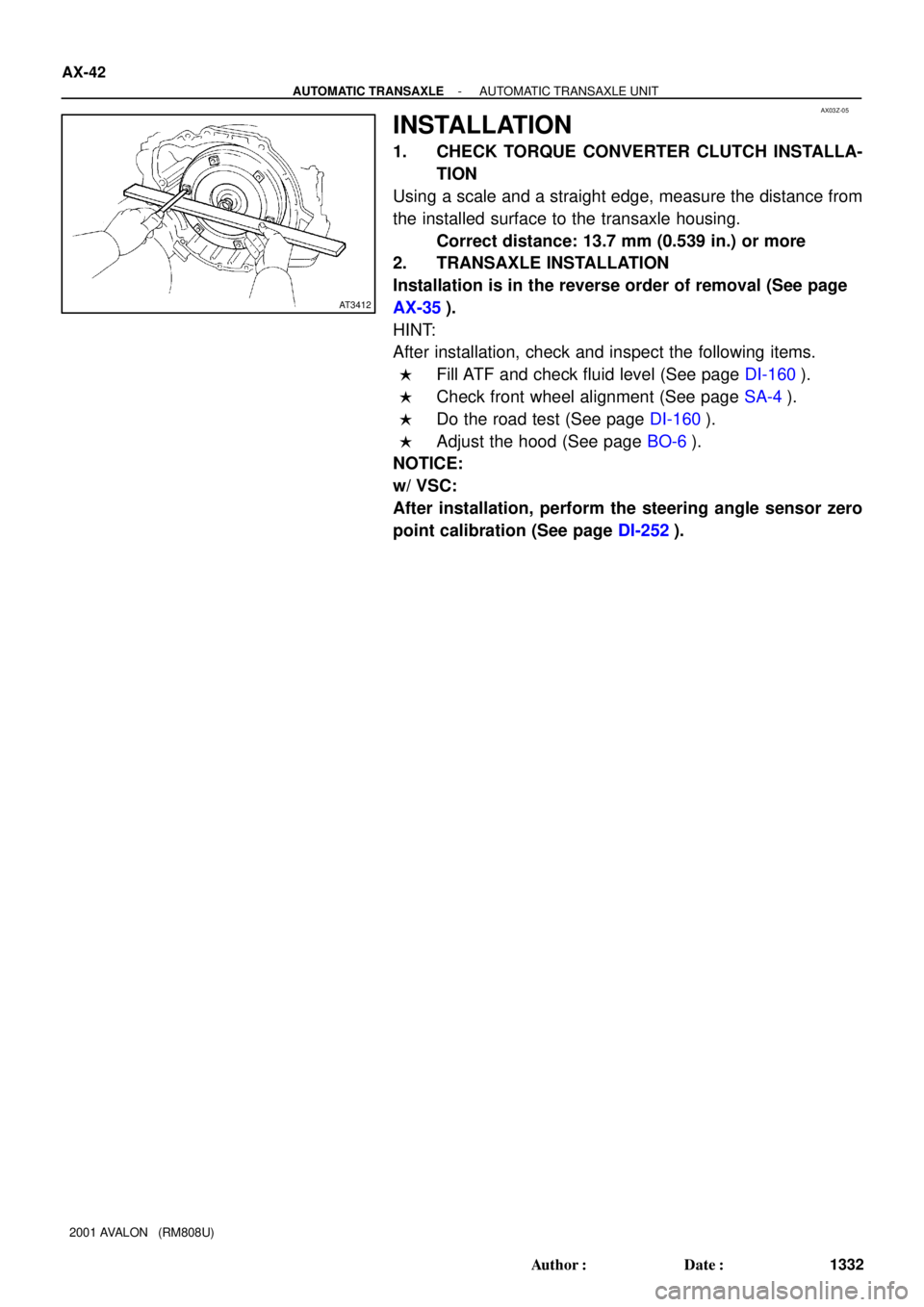
INSTALLATION
1. CHECK TORQUE CONVERTER CLUTCH INSTALLA-
TION
Using a scale and a straight edge, measure the distance from
the installed surface to the transaxle housing.
Correct distance: 13.7 mm (0.539 in.) or more
2. TRANSAXLE INSTALLATION
Installation is in the reverse order of removal (See page
AX-35).
HINT:
After installation, check and inspect the following items.
�Fill ATF and check fluid level (See page DI-160).
�Check front wheel alignment (See page SA-4).
�Do the road test (See page DI-160).
�Adjust the hood (See page BO-6).
NOTICE:
w/ VSC:
After installation, perform the steering angle sensor zero
point calibration (See page DI-252).
Page 98 of 1897
AX0KA-01
A07441
5 mm
Hexagon
Wrench
D04381
V-bank Cover
Fastener
D07234
Q09982
- AUTOMATIC TRANSAXLEAUTOMATIC TRANSAXLE UNIT
AX-35
1325 Author�: Date�:
2001 AVALON (RM808U)
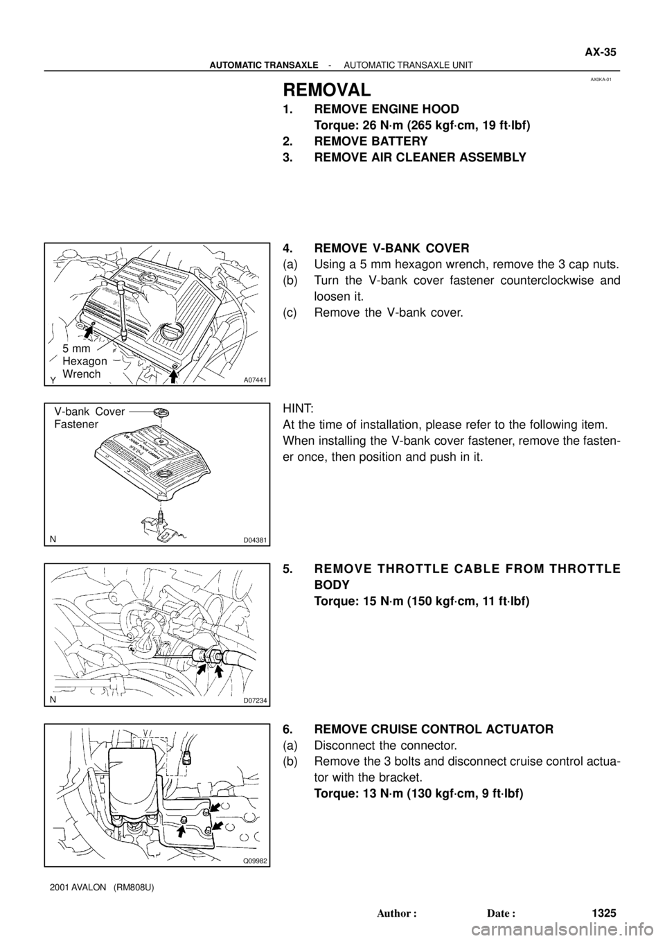
REMOVAL
1. REMOVE ENGINE HOOD
Torque: 26 N´m (265 kgf´cm, 19 ft´lbf)
2. REMOVE BATTERY
3. REMOVE AIR CLEANER ASSEMBLY
4. REMOVE V-BANK COVER
(a) Using a 5 mm hexagon wrench, remove the 3 cap nuts.
(b) Turn the V-bank cover fastener counterclockwise and
loosen it.
(c) Remove the V-bank cover.
HINT:
At the time of installation, please refer to the following item.
When installing the V-bank cover fastener, remove the fasten-
er once, then position and push in it.
5. REMOVE THROTTLE CABLE FROM THROTTLE
BODY
Torque: 15 N´m (150 kgf´cm, 11 ft´lbf)
6. REMOVE CRUISE CONTROL ACTUATOR
(a) Disconnect the connector.
(b) Remove the 3 bolts and disconnect cruise control actua-
tor with the bracket.
Torque: 13 N´m (130 kgf´cm, 9 ft´lbf)
Page 99 of 1897

7. DISCONNECT GROUND CABLE
8. SEPARATE WIRE HARNESS FROM AUTOMATIC
TR")
D07235
Q00075
Q10028
Q06478
Q10286
AX-36
- AUTOMATIC TRANSAXLEAUTOMATIC TRANSAXLE UNIT
1326 Author�: Date�:
2001 AVALON (RM808U)
7. DISCONNECT GROUND CABLE
8. SEPARATE WIRE HARNESS FROM AUTOMATIC
TRANSAXLE
Remove the bolt and separate the wire harness.
9. DISCONNECT DIRECT CLUTCH SPEED SENSOR
CONNECTOR
10. DISCONNECT PARK/NEUTRAL POSITION SWITCH
CONNECTOR
11. DISCONNECT SOLENOID CONNECTOR
12. DISCONNECT SHIFT CONTROL CABLE
(a) Remove the nut and disconnect the shift control cable
from the control shaft lever.
Torque: 15 N´m (150 kgf´cm, 11 ft´lbf)
(b) Remove the clip and disconnect the shift control cable
from the bracket.
13. REMOVE 2 ENGINE MOUNTING ABSORBER BOLTS
Torque: 48 N´m (490 kgf´cm, 35 ft´lbf)
14. REMOVE 2 FRONT SIDE ENGINE MOUNTING BOLTS
Torque: 44 N´m (440 kgf´cm, 32 ft´lbf)
15. REMOVE STARTER AND SHIFT CONTROL CABLE
CLAMP
(a) Disconnect the connector.
(b) Remove the nut and disconnect the terminal.
(c) Remove the 2 bolts, starter and shift control cable clamp.
Torque: 39 N´m (400 kgf´cm, 29 ft´lbf)
Page 100 of 1897
Q06530
Q10038
D07216
Q10037
- AUTOMATIC TRANSAXLEAUTOMATIC TRANSAXLE UNIT
AX-37
1327 Author�: Date�:
2001 AVALON (RM808U)
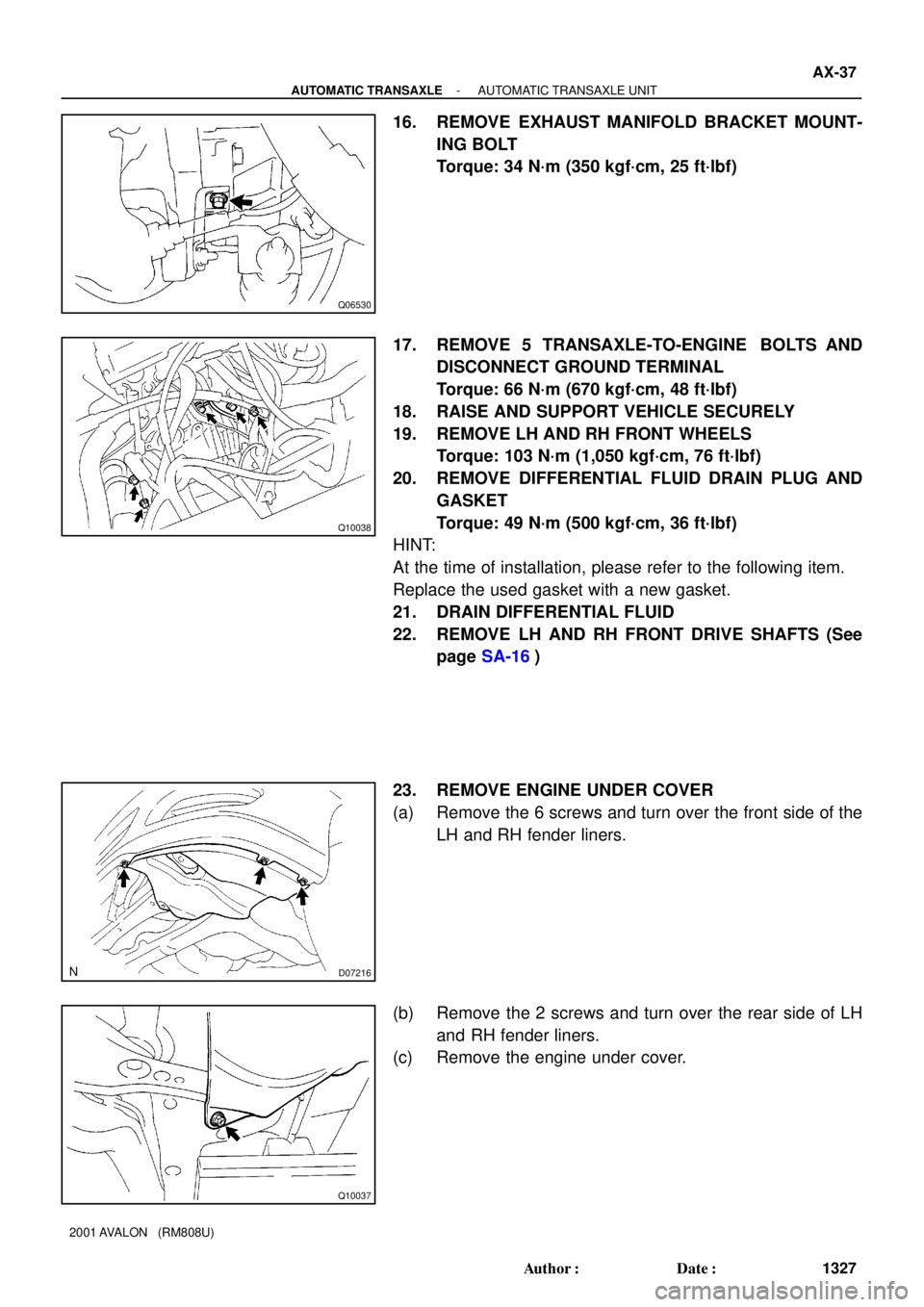
16. REMOVE EXHAUST MANIFOLD BRACKET MOUNT-
ING BOLT
Torque: 34 N´m (350 kgf´cm, 25 ft´lbf)
17. REMOVE 5 TRANSAXLE-TO-ENGINE BOLTS AND
DISCONNECT GROUND TERMINAL
Torque: 66 N´m (670 kgf´cm, 48 ft´lbf)
18. RAISE AND SUPPORT VEHICLE SECURELY
19. REMOVE LH AND RH FRONT WHEELS
Torque: 103 N´m (1,050 kgf´cm, 76 ft´lbf)
20. REMOVE DIFFERENTIAL FLUID DRAIN PLUG AND
GASKET
Torque: 49 N´m (500 kgf´cm, 36 ft´lbf)
HINT:
At the time of installation, please refer to the following item.
Replace the used gasket with a new gasket.
21. DRAIN DIFFERENTIAL FLUID
22. REMOVE LH AND RH FRONT DRIVE SHAFTS (See
page SA-16)
23. REMOVE ENGINE UNDER COVER
(a) Remove the 6 screws and turn over the front side of the
LH and RH fender liners.
(b) Remove the 2 screws and turn over the rear side of LH
and RH fender liners.
(c) Remove the engine under cover.
Page 101 of 1897
D04375
Q00235
Q10027
Q10071
Q10034
AX-38
- AUTOMATIC TRANSAXLEAUTOMATIC TRANSAXLE UNIT
1328 Author�: Date�:
2001 AVALON (RM808U)
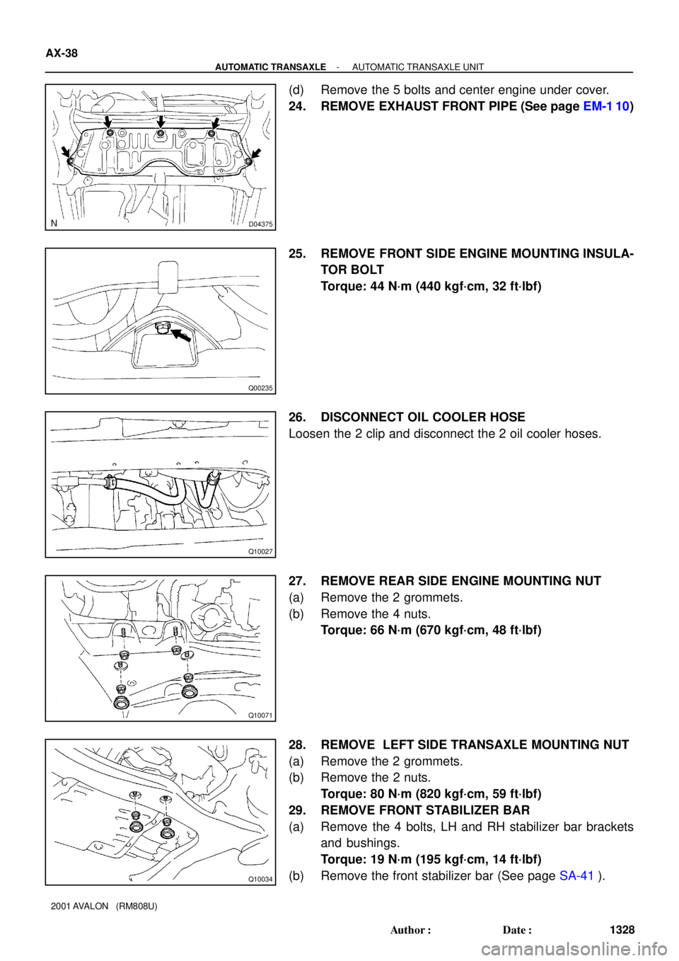
(d) Remove the 5 bolts and center engine under cover.
24. REMOVE EXHAUST FRONT PIPE (See page EM-1 10)
25. REMOVE FRONT SIDE ENGINE MOUNTING INSULA-
TOR BOLT
Torque: 44 N´m (440 kgf´cm, 32 ft´lbf)
26. DISCONNECT OIL COOLER HOSE
Loosen the 2 clip and disconnect the 2 oil cooler hoses.
27. REMOVE REAR SIDE ENGINE MOUNTING NUT
(a) Remove the 2 grommets.
(b) Remove the 4 nuts.
Torque: 66 N´m (670 kgf´cm, 48 ft´lbf)
28. REMOVE LEFT SIDE TRANSAXLE MOUNTING NUT
(a) Remove the 2 grommets.
(b) Remove the 2 nuts.
Torque: 80 N´m (820 kgf´cm, 59 ft´lbf)
29. REMOVE FRONT STABILIZER BAR
(a) Remove the 4 bolts, LH and RH stabilizer bar brackets
and bushings.
Torque: 19 N´m (195 kgf´cm, 14 ft´lbf)
(b) Remove the front stabilizer bar (See page SA-41).
Page 102 of 1897
D02910
P19478
Engine
Hanger
Q06479
- AUTOMATIC TRANSAXLEAUTOMATIC TRANSAXLE UNIT
AX-39
1329 Author�: Date�:
2001 AVALON (RM808U)
30. TIE STEERING GEAR ASSEMBLY WITH CODE OR
EQUIVALENT TO SUSPEND ASSEMBLY SECURELY,
AS SHOWN
31. REMOVE 2 STEERING GEAR ASSEMBLY MOUNTING
BOLTS
Torque: 181 N´m (1,850 kgf´cm, 134 ft´lbf)
32. ATTACH ENGINE SLING DEVICE TO ENGINE HANG-
ERS
(a) Install the No.2 engine hangers in the correct direction.
Part No.:
No.2 engine hanger: 12282-20020
Bolt: 91621-60822
Torque: 20 N´m (200 kgf´cm, 14 ft´lbf)
(b) Attach the engine chain hoist to the engine hangers.
CAUTION:
Do not attempt to hang the engine by hooking the chain to
any other part.
33. REMOVE FRONT FRAME ASSEMBLY
(a) Remove the 2 bolts and PS reservoir pipe mounting
brackets.
Torque: 10 N´m (100 kgf´cm, 7 ft´lbf)