Page 100 of 1897
Q06530
Q10038
D07216
Q10037
- AUTOMATIC TRANSAXLEAUTOMATIC TRANSAXLE UNIT
AX-37
1327 Author�: Date�:
2001 AVALON (RM808U)
16. REMOVE EXHAUST MANIFOLD BRACKET MOUNT-
ING BOLT
Torque: 34 N´m (350 kgf´cm, 25 ft´lbf)
17. REMOVE 5 TRANSAXLE-TO-ENGINE BOLTS AND
DISCONNECT GROUND TERMINAL
Torque: 66 N´m (670 kgf´cm, 48 ft´lbf)
18. RAISE AND SUPPORT VEHICLE SECURELY
19. REMOVE LH AND RH FRONT WHEELS
Torque: 103 N´m (1,050 kgf´cm, 76 ft´lbf)
20. REMOVE DIFFERENTIAL FLUID DRAIN PLUG AND
GASKET
Torque: 49 N´m (500 kgf´cm, 36 ft´lbf)
HINT:
At the time of installation, please refer to the following item.
Replace the used gasket with a new gasket.
21. DRAIN DIFFERENTIAL FLUID
22. REMOVE LH AND RH FRONT DRIVE SHAFTS (See
page SA-16)
23. REMOVE ENGINE UNDER COVER
(a) Remove the 6 screws and turn over the front side of the
LH and RH fender liners.
(b) Remove the 2 screws and turn over the rear side of LH
and RH fender liners.
(c) Remove the engine under cover.
Page 106 of 1897
Q00394
SST
AX03S-05
Q06348
SST
Q00238
SST AX-14
- AUTOMATIC TRANSAXLEDIFFERENTIAL OIL SEAL
1304 Author�: Date�:
2001 AVALON (RM808U)
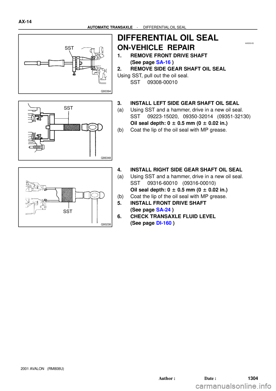
DIFFERENTIAL OIL SEAL
ON-VEHICLE REPAIR
1. REMOVE FRONT DRIVE SHAFT
(See page SA-16)
2. REMOVE SIDE GEAR SHAFT OIL SEAL
Using SST, pull out the oil seal.
SST 09308-00010
3. INSTALL LEFT SIDE GEAR SHAFT OIL SEAL
(a) Using SST and a hammer, drive in a new oil seal.
SST 09223-15020, 09350-32014 (09351-32130)
Oil seal depth: 0 ± 0.5 mm (0 ± 0.02 in.)
(b) Coat the lip of the oil seal with MP grease.
4. INSTALL RIGHT SIDE GEAR SHAFT OIL SEAL
(a) Using SST and a hammer, drive in a new oil seal.
SST 09316-60010 (09316-00010)
Oil seal depth: 0 ± 0.5 mm (0 ± 0.02 in.)
(b) Coat the lip of the oil seal with MP grease.
5. INSTALL FRONT DRIVE SHAFT
(See page SA-24)
6. CHECK TRANSAXLE FLUID LEVEL
(See page DI-160)
Page 775 of 1897

(b) Clearance the DTC.
The following operation will erase the DTC and freeze
frame data. Operating an OBD II scan too")
DI-164
- DIAGNOSTICSAUTOMATIC TRANSAXLE
320 Author�: Date�:
2001 AVALON (RM808U)
(b) Clearance the DTC.
The following operation will erase the DTC and freeze
frame data. Operating an OBD II scan tool (complying
with SAE J1978) or TOYOTA hand-held tester to erase
the codes (See the OBD II scan tool's instruction book for
operating instructions.).
4. ROAD TEST
NOTICE:
Perform the test at normal operating ATF temperature 50 - 80 °C (122 - 176 °F).
(a) D position test
Shift into the D position and fully depress the accelerator pedal and check the following points:
(1) Check up-shift operation.
Check to see that 1 " 2, 2 " 3 and 3 " O/D up-shift takes place,and that the shift points conform
the automatic shift schedule (See page SS-24).
HINT:
�O/D Gear Up-shift Prohibition Control (1. Coolant temp. is 60 °C (140 °F) or less. 2. If there is a 10
km/h (6 mph) difference between the set cruise control speed and vehicle speed.)
�O/D Gear Lock-up Prohibition Control (1. Brake pedal is depressed. 2. Coolant temp. is 60 °C (140
°F) or less.)
(2) Check for shift shock and slip.
Check for shock and slip at the 1 " 2, 2 " 3 and 3 " O/D up-shifts.
(3) Check for abnormal noises and vibration.
Run at the D position lock-up or O/D gear and check for abnormal noises and vibration.
HINT:
The check for the cause of abnormal noises and vibration must be done very thoroughly as it could also be
due to loss of balance in the differential torque converter clutch, etc.
(4) Check kick-down operation.
While running in the D position, 2nd, 3rd and O/D gears, check to see that the possible kick-down
vehicle speed limits for 2 " 1, 3 " 2 and O/D " 3 kick-downs conform to those indicated in the
automatic shift schedule (See page SS-24).
(5) Check abnormal shock and slip at kick-down.
(6) Check the lock-up mechanism.
�Drive in D position, O/D gear, at a steady speed (lock-up ON) of about 60 km/h (37 mph).
�Lightly depress the accelerator pedal and check that the engine speed does not change
abruptly.
If there is a big jump in engine speed, there is no lock-up.
(b) 2 position test
Shift into the 2 position and fully depress the accelerator pedal and check the following points:
(1) Check up-shift operation.
Check to see that the 1 " 2 up-shift takes place and that the shift point conforms to the automatic
shift schedule (See page SS-24).
HINT:
There is no O/D up-shift and lock-up in the 2 position.
(2) Check engine braking.
While running in the 2 position and 2nd gear, release the accelerator pedal and check the engine
braking effect.
(3) Check for abnormal noises during acceleration and deceleration, and for shock at up-shift and
down-shift.
Page 1440 of 1897

TERMS
ABBREVIATIONS USED IN THIS MANUAL
AbbreviationsMeaning
ABSAnti-Lock Brake System
ACAlternating Current
ACCAccessory")
IN04Q-08
- INTRODUCTIONTERMS
IN-35
35 Author�: Date�:
2001 AVALON (RM808U)
TERMS
ABBREVIATIONS USED IN THIS MANUAL
AbbreviationsMeaning
ABSAnti-Lock Brake System
ACAlternating Current
ACCAccessory
ACISAcoustic Control Induction System
ACSDAutomatic Cold Start Device
A.D.D.Automatic Disconnecting Differential
A/FAir-Fuel Ratio
AHCActive Height Control Suspension
ALRAutomatic Locking Retractor
ALTAlternator
AMPAmplifier
ANTAntenna
APPROX.Approximately
A/TAutomatic Transmission (Transaxle)
AT FAutomatic Transmission Fluid
AUTOAutomatic
AUXAuxiliary
AV GAverage
AV SAdaptive Variable Suspension
BABrake Assist
BACSBoost Altitude Compensation System
BATBattery
BDCBottom Dead Center
B/LBi-Level
B/SBore-Stroke Ratio
BTDCBefore Top Dead Center
BVSVBimetallic Vacuum Switching Valve
Calif.California
CBCircuit Breaker
CCoCatalytic Converter For Oxidation
CDCompact Disc
CFCornering Force
CGCenter Of Gravity
CHChannel
COMB.Combination
CPECoupe
CPSCombustion Pressure Sensor
CPUCentral Processing Unit
CRSChild Restraint System
CTRCenter
C/VCheck Valve
CVControl Valve
Page 1441 of 1897
 CW
Curb Weight
DCDirect Current
DEFDefogger
DFLDeflector
DIFF.Differential
DIFF. LOCKDifferential Lock
D/INJDirect Injection
DLIDist")
IN-36
- INTRODUCTIONTERMS
36 Author�: Date�:
2001 AVALON (RM808U) CW
Curb Weight
DCDirect Current
DEFDefogger
DFLDeflector
DIFF.Differential
DIFF. LOCKDifferential Lock
D/INJDirect Injection
DLIDistributorless Ignition
DOHCDouble Over Head Cam
DPDash Pot
DSDead Soak
DSPDigital Signal Processor
EBDElectronic Brake Force Distribution
ECAMEngine Control And Measurement System
ECDElectronic Controlled Diesel
ECDYEddy Current Dynamometer
ECUElectronic Control Unit
EDElectro-Deposited Coating
EDUElectronic Driving Unit
EDICElectric Diesel Injection Control
EFIElectronic Fuel Injection
E/GEngine
EGR-VMEgr-Vacuum Modulator
ELREmergency Locking Retractor
ENGEngine
ESAElectronic Spark Advance
ETCSElectronic Throttle Control System
EVPEvaporator
E-VR VElectric Vacuum Regulating Valve
EXHExhaust
FEFuel Economy
FFFront-Engine Front-Wheel-Drive
F/GFuel Gage
FIPGFormed In Place Gasket
FLFusible Link
F/PFuel Pump
FPUFuel Pressure Up
FrFront
FRFront-Engine Rear-Wheel-Drive
F/WFlywheel
FW/DFlywheel Damper
FWDFront-Wheel-Drive
GASGasoline
GNDGround
HACHigh Altitude Compensator
H/BHatchback
Page 1442 of 1897
 H-FUSE
High Current Fuse
HIHigh
HIDHigh Intensity Discharge (Head Lamp)
HSGHousing
HTHard Top
HWSHeated Windshield System
IACIdle Ai")
- INTRODUCTIONTERMS
IN-37
37 Author�: Date�:
2001 AVALON (RM808U) H-FUSE
High Current Fuse
HIHigh
HIDHigh Intensity Discharge (Head Lamp)
HSGHousing
HTHard Top
HWSHeated Windshield System
IACIdle Air Control
ICIntegrated circuit
IDIIndirect Diesel Injection
IFSIndependent Front Suspension
IGIgnition
IIAIntegrated Ignition Assembly
INIntake (Manifold, Valve)
INTIntermittent
I/PInstrument Panel
IRSIndependent Rear Suspension
J/BJunction Block
J/CJunction Connector
KDKick-Down
LANLocal Area Network
LBLiftback
LCDLiquid Crystal Display
LEDLight Emitting Diode
LHLeft-Hand
LHDLeft-Hand Drive
L/H/WLength, Height, Width
LLCLong-Life Coolant
LNGLiquified Natural Gas
LOLow
LPGLiquified Petroleum Gas
LSDLimited Slip Differential
LSP & PVLoad Sensing Proportioning And Bypass Valve
LSPVLoad Sensing Proportioning Valve
MAX.Maximum
MICMicrophone
MILMalfunction Indicator Lamp
MIN.Minimum
MPMultipurpose
MPXMultiplex Communication System
M/TManual Transmission
MTMount
MTGMounting
NNeutral
NANatural Aspiration
No.Number
O/DOverdrive
Page 1446 of 1897
 HO2S
Heated Oxygen SensorHeated Oxygen Sensor (HO2S)
IACIdle Air ControlIdle Speed Control (ISC)
IATIntake Air TemperatureIntake or")
- INTRODUCTIONTERMS
IN-41
41 Author�: Date�:
2001 AVALON (RM808U) HO2S
Heated Oxygen SensorHeated Oxygen Sensor (HO2S)
IACIdle Air ControlIdle Speed Control (ISC)
IATIntake Air TemperatureIntake or Inlet Air Temperature
ICMIgnition Control Module-
IFIIndirect Fuel InjectionIndirect Injection (IDL)
IFSInertia Fuel-Shutoff-
ISCIdle Speed Control-
KSKnock SensorKnock Sensor
MAFMass Air FlowAir Flow Meter
MAPManifold Absolute PressureManifold Pressure
Intake Vacuum
MCMixture Control
Electric Bleed Air Control Valve (EBCV)
Mixture Control Valve (MCV)
Electric Air Control Valve (EACV)
MDPManifold Differential Pressure-
MFIMultiport Fuel InjectionElectronic Fuel Injection (EFI)
MILMalfunction Indicator LampCheck Engine Lamp
MSTManifold Surface Temperature-
MVZManifold Vacuum Zone-
NVRAMNon-V olatile Random Access Memory-
O2SOxygen SensorOxygen Sensor, O2 Sensor (O2S)
OBDOn-Board DiagnosticOn-Board Diagnostic System (OBD)
OCOxidation Catalytic ConverterOxidation Catalyst Convert (OC), CCo
OPOpen LoopOpen Loop
PAIRPulsed Secondary Air InjectionAir Suction (AS)
PCMPowertrain Control Module-
PNPPark/Neutral Position-
PROMProgrammable Read Only Memory-
PSPPower Steering Pressure-
PTOXPeriodic Trap OxidizerDiesel Particulate Filter (DPF)
Diesel Particulate Trap (DPT)
RAMRandom Access MemoryRandom Access Memory (RAM)
RMRelay Module-
ROMRead Only MemoryRead Only Memory (ROM)
RPMEngine SpeedEngine Speed
SCSuperchargerSupercharger
SCBSupercharger BypassE-ABV
SFISequential Multiport Fuel InjectionElectronic Fuel Injection (EFI), Sequential Injection
SPLSmoke Puff Limiter-
SRIService Reminder Indicator-
SRTSystem Readiness Test-
STScan Tool-
TBThrottle BodyThrottle Body
TBIThrottle Body Fuel InjectionSingle Point Injection
Central Fuel Injection (Ci)
TCTurbochargerTurbocharger
TCCTorque Converter ClutchTorque Converter
Page 1482 of 1897
PP0M4-05
- PREPARATIONAUTOMATIC TRANSAXLE
PP-31
81 Author�: Date�:
2001 AVALON (RM808U)
LUBRICANT
ItemCapacityClassification
Automatic transaxle fluid
(w/o Differential oil)
Dry fill
Drain and refill
8.0 liters (8.5 US qts, 7.0 Imp. qts)
4.75 liters (5.0 US qts, 4.2 Imp. qts)ATF D-II or DEXRON®III (DEXRON®II)