Page 1454 of 1897
B08905
N´m (kgf´cm, ft´lbf): Specified torque
� Non-reusable partNo.3 Timing Belt Cover
Gasket
BushingCollar
A/C Compressor
Housing Bracket
Oil Pan Baffle Plate Crankshaft
Position Sensor
Connector Crankshaft
Position
Sensor
Oil PumpEngine Wire
Oil Strainer
No.2 Oil Pan
x 10x 6
x 9� O-Ring
No.1 Oil Pan
� Gasket
Drain Plug
8.5 (85, 74 in.´lbf)
8 (80, 69 in.´lbf)
8 (80, 69 in.´lbf)
10 mm Head 8 (80, 69 in.´lbf)
12 mm Head 19.5 (200, 14)
10 mm Head 8 (80, 69 in.´lbf)
12 mm Head 19.5 (200, 14)
14 mm Head 37.2 (380, 27)
8 (80, 69 in.´lbf)
45 (460, 33)
8 (80, 69 in.´lbf)
x 6
x 17
� Gasket
19.5 (200, 14)
No.1 Exhaust Pipe
Support Bracket
- LUBRICATIONOIL PUMP
LU-7
1232 Author�: Date�:
2001 AVALON (RM808U)
Page 1460 of 1897

(d) Install the No.1 exhaust pipe support bracket with the 2
bolts.
Torque: 7.8 N´m (80 kgf´")
P12568
AB
Seal Width
4 - 5 mm A
B
- LUBRICATIONOIL PUMP
LU-17
1242 Author�: Date�:
2001 AVALON (RM808U)
(d) Install the No.1 exhaust pipe support bracket with the 2
bolts.
Torque: 7.8 N´m (80 kgf´cm, 69 in.´lbf)
5. INSTALL OIL STRAINER
Install a new gasket and the oil strainer with the bolt and 2 nuts.
Torque: 8 N´m (80 kgf´cm, 69 in.´lbf)
6. INSTALL NO.2 OIL PAN
(a) Remove any old packing (FIPG) material and be careful
not to drop any oil on the contact surface of the No.1 and
No.2 oil pans.
�Using a razor blade and gasket scraper, remove all
the old packing (FIPG) material from the gasket sur-
faces and sealing grooves.
�Thoroughly clean all components to remove all the
loose material.
�Using a non-residue solvent, clean both sealing
surfaces.
NOTICE:
Do not use a solvent which will affect the painted surfaces.
(b) Apply seal packing to the No.2 oil pan as shown in the il-
lustration.
Seal packing: Part No. 08826-00080 or equivalent
�Install a nozzle that has been cut to a 4 - 5 mm (0.16
- 0.20 in.) opening.
HINT:
Avoid applying an excessive amount to the surface.
�Parts must be assembled within 3 minutes of ap-
plication. Otherwise the material must be removed
and reapplied.
�Immediately remove nozzle from the tube and rein-
stall cap.
(c) Install the No.2 oil pan with the 10 bolts and 2 nuts. Uni-
formly tighten the bolts and nuts in several passes.
Torque: 8 N´m (80 kgf´cm, 69 in.´lbf)
7. INSTALL TIMING PULLEYS (See page EM-21)
8. INSTALL TIMING BELT (See page EM-21)
Page 1463 of 1897
LU0IB-01
P18778
Pivot
Bolt
Adjusting
Strut
Adjusting Bolt
B04135
P18801
- LUBRICATIONOIL PUMP
LU-9
1234 Author�: Date�:
2001 AVALON (RM808U)
REMOVAL
HINT:
When repairing the oil pump, the oil pan and strainer should be
removed and cleaned.
1. DRAIN ENGINE OIL
2. REMOVE RH FRONT WHEEL
3. REMOVE RH FENDER APRON SEAL
4. REMOVE FRONT EXHAUST PIPE
(See page EM-72)
5. REMOVE GENERATOR FROM ENGINE
(See page CH-6)
6. REMOVE A/C COMPRESSOR FROM ENGINE
(See page EM-72)
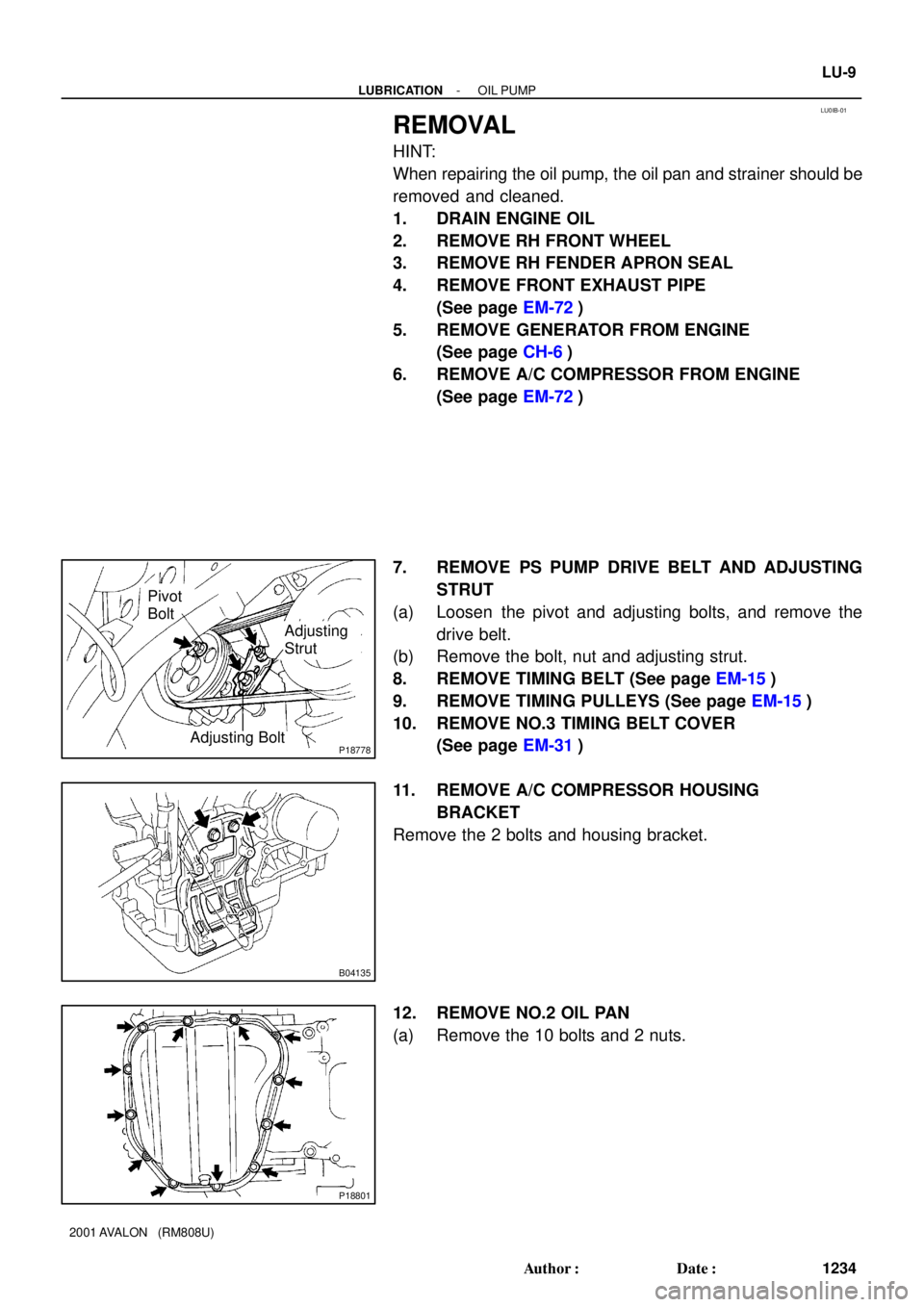
7. REMOVE PS PUMP DRIVE BELT AND ADJUSTING
STRUT
(a) Loosen the pivot and adjusting bolts, and remove the
drive belt.
(b) Remove the bolt, nut and adjusting strut.
8. REMOVE TIMING BELT (See page EM-15)
9. REMOVE TIMING PULLEYS (See page EM-15)
10. REMOVE NO.3 TIMING BELT COVER
(See page EM-31)
11. REMOVE A/C COMPRESSOR HOUSING
BRACKET
Remove the 2 bolts and housing bracket.
12. REMOVE NO.2 OIL PAN
(a) Remove the 10 bolts and 2 nuts.
Page 1469 of 1897
MA01M-02
P00495
Inside Outside
- MAINTENANCEENGINE
MA-5
47 Author�: Date�:
2001 AVALON (RM808U)
ENGINE
INSPECTION
HINT:
Inspect these items when the engine is cold.
1. REPLACE TIMING BELT (See page EM-15)
2. INSPECT DRIVE BELTS
(See pages CH-1, SR-3 and AC-17)
3. REPLACE SPARK PLUGS (See page IG-1)
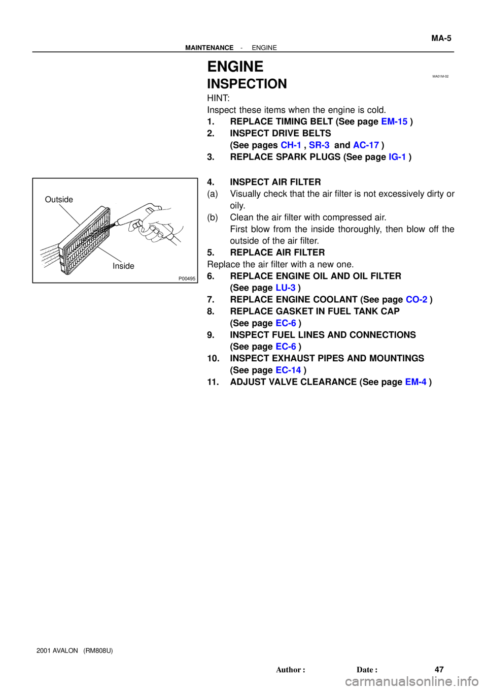
4. INSPECT AIR FILTER
(a) Visually check that the air filter is not excessively dirty or
oily.
(b) Clean the air filter with compressed air.
First blow from the inside thoroughly, then blow off the
outside of the air filter.
5. REPLACE AIR FILTER
Replace the air filter with a new one.
6. REPLACE ENGINE OIL AND OIL FILTER
(See page LU-3)
7. REPLACE ENGINE COOLANT (See page CO-2)
8. REPLACE GASKET IN FUEL TANK CAP
(See page EC-6)
9. INSPECT FUEL LINES AND CONNECTIONS
(See page EC-6)
10. INSPECT EXHAUST PIPES AND MOUNTINGS
(See page EC-14)
11. ADJUST VALVE CLEARANCE (See page EM-4)
Page 1564 of 1897

ENGINE MECHANICAL
SERVICE DATA
Compression
pressureat 250 rpm STD
Minimum
Difference of pressure bet")
SS0EF-02
SS-6
- SERVICE SPECIFICATIONSENGINE MECHANICAL
122 Author�: Date�:
2001 AVALON (RM808U)
ENGINE MECHANICAL
SERVICE DATA
Compression
pressureat 250 rpm STD
Minimum
Difference of pressure between each cylinder1,500 kPa (15.3 kgf/cm2, 218 psi)
1,000 kPa (10.2 kgf/cm2, 145 psi)
100 kPa (1.0 kgf/cm2, 15 psi) or less
Valve
clearanceat cold Intake
Exhaust
Adjusting shim for repair part Mark 2.500
Mark 2.550
Mark 2.600
Mark 2.650
Mark 2.700
Mark 2.750
Mark 2.800
Mark 2.850
Mark 2.900
Mark 2.950
Mark 3.000
Mark 3.050
Mark 3.100
Mark 3.150
Mark 3.200
Mark 3.250
Mark 3.3000.15 - 0.25 mm (0.006 - 0.010 in.)
0.25 - 0.35 mm (0.010 - 0.014 in.)
2.500 mm (0.0984 in.)
2.550 mm (0.1004 in.)
2.600 mm (0.1024 in.)
2.650 mm (0.1043 in.)
2.700 mm (0.1063 in.)
2.750 mm (0.1083 in.)
2.800 mm (0.1102 in.)
2.850 mm (0.1122 in.)
2.900 mm (0.1142 in.)
2.950 mm (0.1161 in.)
3.000 mm (0.1181 in.)
3.050 mm (0.1201 in.)
3.100 mm (0.1220 in.)
3.150 mm (0.1240 in.)
3.200 mm (0.1260 in.)
3.250 mm (0.1280 in.)
3.300 mm (0.1299 in.)
Ignition timingw/ Terminals TE1 and E1 connected of DLC18 - 12° BTDC @ idle
Idle speed-650 ± 50 rpm
Timing belt
tensionerProtrusion from housing side10.0 - 10.8 mm (0.394 - 0.425 in.)
Cylinder headWarpage Maximum
Valve seat
Refacing angle
Contacting angle
Contacting width
Valve guide bushing bore diameter STD
O/S 0.05
12 pointed head cylinder head bolt diameter
at tension portion STD
Minimum0.10 mm (0.039 in.)
30°, 45°, 75°
45°
1.0 - 1.4 mm (0.039 - 0.055 in.)
10.295 - 10.313 mm (0.4053 - 0.4080 in.)
10.345 - 10.363 mm (0.4073 - 0.4080 in.)
8.95 - 9.05 mm (0.3524 - 0.3563 in.)
8.75 mm (0.3445 in.)
Valve guide
bushingInside diameter
Outside diameter for repair part STD
O/S 0.055.510 - 5.530 mm (0.2169 - 0.2177 in.)
10.333 - 10.344 mm (0.4068 - 0.4072 in.)
10.383 - 10.394 mm (0.4088 - 0.4092 in.)
ValveValve overall length STD Intake
Exhaust
Minimum Intake
Exhaust
Valve face angle
Stem diameterIntake
Exhaust
Stem oil clearance STD Intake
Exhaust
Maximum Intake
Exhaust
Margin thickness STD
Maximum95.45 mm (3.5779 in.)
95.40 mm (3.7559 in.)
94.95 mm (3.7382 in.)
94.90 mm (3.7362 in.)
44.5°
5.470 - 5.485 mm (0.2154 - 0.2159 in.)
5.465 - 5.480 mm (0.2152 - 0.2157 in.)
0.025 - 0.060 mm (0.0010 - 0.0024 in.)
0.030 - 0.065 mm (0.0012 - 0.0026 in.)
0.08 mm (0.0031 in.)
0.10 mm (0.0039 in.)
1.0 mm (0.039 in.)
0.5 mm (0.020 in.)
Page 1567 of 1897

TORQUE SPECIFICATION
Part tightenedN´mkgf´cmft´lbf
Timing belt plate x Oil pump88069 in.´lbf
No.1")
SS0EG-02
- SERVICE SPECIFICATIONSENGINE MECHANICAL
SS-9
125 Author�: Date�:
2001 AVALON (RM808U)
TORQUE SPECIFICATION
Part tightenedN´mkgf´cmft´lbf
Timing belt plate x Oil pump88069 in.´lbf
No.1 idler pulley x Oil pump3435025
No.2 idler pulley x No.2 idler pulley bracket4344032
Camshaft timing pulley x Camshaft
for SST125
881,300
90094
65
Timing belt tensioner x Oil pump2728020
RH engine mounting bracket x Cylinder block2829021
No.2 timing belt cover x No.3 timing belt cover8.58574 in.´lbf
No.1 timing belt cover x Oil pump8.58574 in.´lbf
Crankshaft pulley x Crankshaft2152,200159
No.2 generator bracket x Engine RH mounting bracket2829021
Cylinder head x Cylinder block 12 pointed head 1st
2nd
Recessed head54
Turn 90°
18.5550
Turn 90°
18540
Turn 90°
13
Camshaft bearing cap x Cylinder head1616012
Cylinder head cover x Cylinder head88069 in.´lbf
Exhaust manifold x Cylinder head4950036
Exhaust manifold stay x Exhaust manifold California
Except California34
20350
20025
15
Exhaust manifold stay x Transmission housing California
Except California34
20350
20025
15
No.1 EGR pipe x RH exhaust manifold121209
No.1 EGR pipe x EGR cooler121209
PS pump bracket x RH cylinder head4344032
Oil dipstick guide x LH cylinder head88069 in.´lbf
Water inlet pipe x LH cylinder head19.520014
Cylinder head rear plate x LH cylinder head88069 in.´lbf
No.3 timing belt cover x Cylinder head8.58574 in.´lbf
Water outlet x Intake manifold1515011
Fuel inlet hose x Fuel filter2930021
Intake manifold x Cylinder head1515011
Air intake chamber x Intake manifold4344032
No.2 EGR pipe x Air intake chamber121209
No.2 EGR pipe x EGR cooler121209
No.1 engine hanger x Air intake chamber3940029
No.1 engine hanger x RH cylinder head3940029
Air intake chamber stay x Air intake chamber19.520014
Air intake chamber stay x RH cylinder head19.520014
Main bearing cap x Cylinder block 12 pointed head 1st
2nd
6 pointed head22
Turn 90°
27225
Turn 90°
27516
Turn 90°
20
Connecting rod cap x Connecting rod 1st
2nd24.5
Turn 90°250
Turn 90°18
Turn 90°
Rear oil seal retainer x Cylinder block88069 in.´lbf
EGR cooler x Cylinder block99078 in.´lbf