Page 560 of 1897
P10834
SST (A)
SST (C)Insert
P10829
SST (C)
SST (A)
Turn
P10836
SST (A) Turn
SST (B)
P00428
P00645
CH-14
- CHARGINGGENERATOR
1287 Author�: Date�:
2001 AVALON (RM808U)
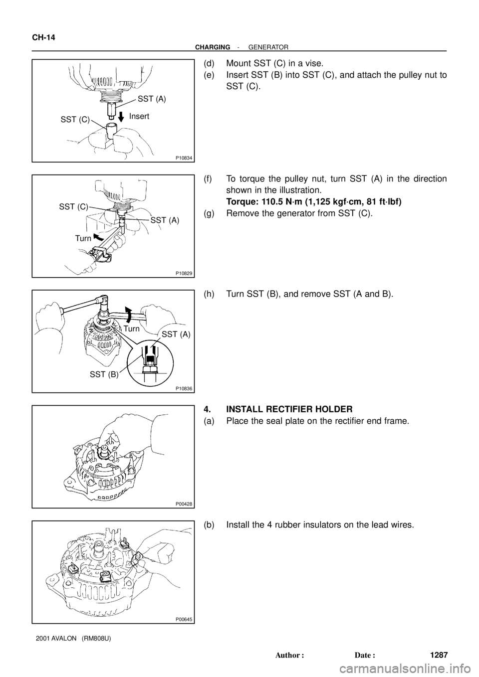
(d) Mount SST (C) in a vise.
(e) Insert SST (B) into SST (C), and attach the pulley nut to
SST (C).
(f) To torque the pulley nut, turn SST (A) in the direction
shown in the illustration.
Torque: 110.5 N´m (1,125 kgf´cm, 81 ft´lbf)
(g) Remove the generator from SST (C).
(h) Turn SST (B), and remove SST (A and B).
4. INSTALL RECTIFIER HOLDER
(a) Place the seal plate on the rectifier end frame.
(b) Install the 4 rubber insulators on the lead wires.
Page 561 of 1897
P20103
S05460
Upward
P14235
P14233
Plate Terminal
P20102
- CHARGINGGENERATOR
CH-15
1288 Author�: Date�:
2001 AVALON (RM808U)
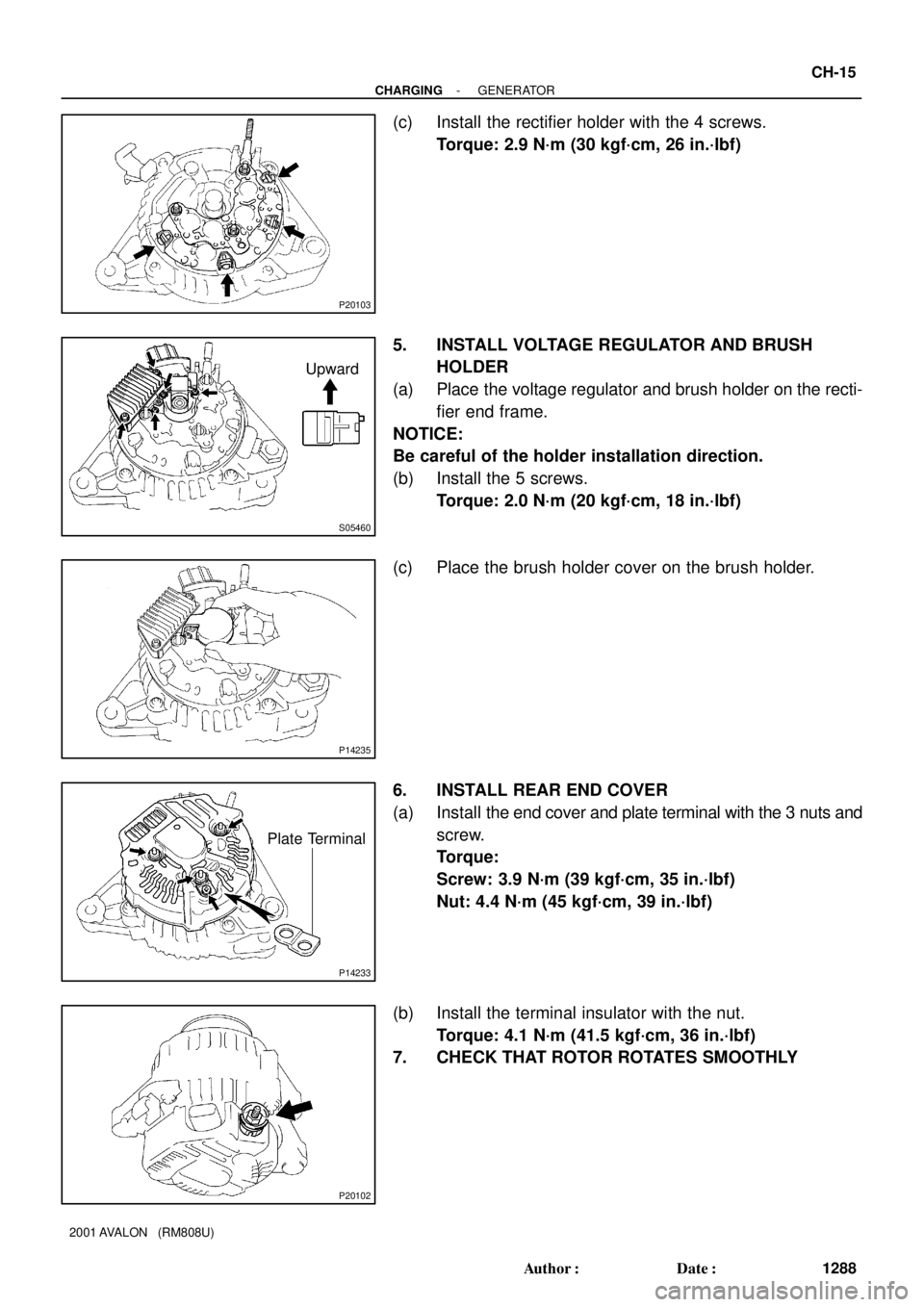
(c) Install the rectifier holder with the 4 screws.
Torque: 2.9 N´m (30 kgf´cm, 26 in.´lbf)
5. INSTALL VOLTAGE REGULATOR AND BRUSH
HOLDER
(a) Place the voltage regulator and brush holder on the recti-
fier end frame.
NOTICE:
Be careful of the holder installation direction.
(b) Install the 5 screws.
Torque: 2.0 N´m (20 kgf´cm, 18 in.´lbf)
(c) Place the brush holder cover on the brush holder.
6. INSTALL REAR END COVER
(a) Install the end cover and plate terminal with the 3 nuts and
screw.
Torque:
Screw: 3.9 N´m (39 kgf´cm, 35 in.´lbf)
Nut: 4.4 N´m (45 kgf´cm, 39 in.´lbf)
(b) Install the terminal insulator with the nut.
Torque: 4.1 N´m (41.5 kgf´cm, 36 in.´lbf)
7. CHECK THAT ROTOR ROTATES SMOOTHLY
Page 562 of 1897
CH03W-02
P19938
P19978
CH-6
- CHARGINGGENERATOR
1279 Author�: Date�:
2001 AVALON (RM808U)
REMOVAL
1. REMOVE DRIVE BELT
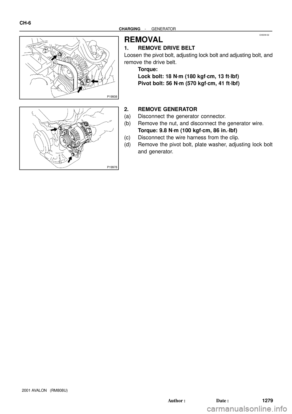
Loosen the pivot bolt, adjusting lock bolt and adjusting bolt, and
remove the drive belt.
Torque:
Lock bolt: 18 N´m (180 kgf´cm, 13 ft´lbf)
Pivot bolt: 56 N´m (570 kgf´cm, 41 ft´lbf)
2. REMOVE GENERATOR
(a) Disconnect the generator connector.
(b) Remove the nut, and disconnect the generator wire.
Torque: 9.8 N´m (100 kgf´cm, 86 in.´lbf)
(c) Disconnect the wire harness from the clip.
(d) Remove the pivot bolt, plate washer, adjusting lock bolt
and generator.
Page 563 of 1897
CH03Z-02
P14225
P00628
Socket Wrench
P00479
SST
N00581
SST
P13567
- CHARGINGGENERATOR
CH-1 1
1284 Author�: Date�:
2001 AVALON (RM808U)
REPLACEMENT
1. REPLACE FRONT BEARING
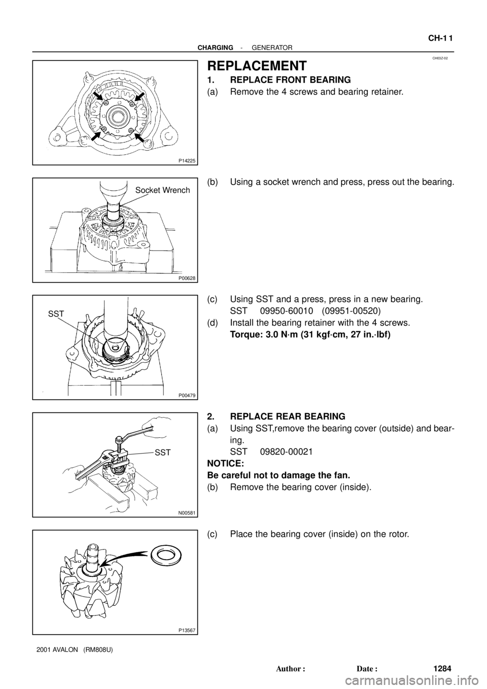
(a) Remove the 4 screws and bearing retainer.
(b) Using a socket wrench and press, press out the bearing.
(c) Using SST and a press, press in a new bearing.
SST 09950-60010 (09951-00520)
(d) Install the bearing retainer with the 4 screws.
Torque: 3.0 N´m (31 kgf´cm, 27 in.´lbf)
2. REPLACE REAR BEARING
(a) Using SST,remove the bearing cover (outside) and bear-
ing.
SST 09820-00021
NOTICE:
Be careful not to damage the fan.
(b) Remove the bearing cover (inside).
(c) Place the bearing cover (inside) on the rotor.
Page 564 of 1897
N00578
SST
P00074
SST
CH-12
- CHARGINGGENERATOR
1285 Author�: Date�:
2001 AVALON (RM808U)
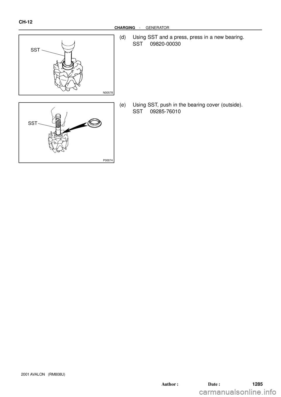
(d) Using SST and a press, press in a new bearing.
SST 09820-00030
(e) Using SST, push in the bearing cover (outside).
SST 09285-76010
Page 592 of 1897
CO02M-03
A10834
RH Fender Apron Seal
Generator Drive Belt
Engine Moving
Control Rod
No.2 RH Engine
Mounting Bracket
Ground Strap
Connector PS Pump Drive Belt
Engine Coolant Reservoir Hose
: Specified torque
64 (650, 47)
32 (320, 23)
N´m (kgf´cm, ft´lbf)
- COOLINGWATER PUMP
CO-3
1196 Author�: Date�:
2001 AVALON (RM808U)
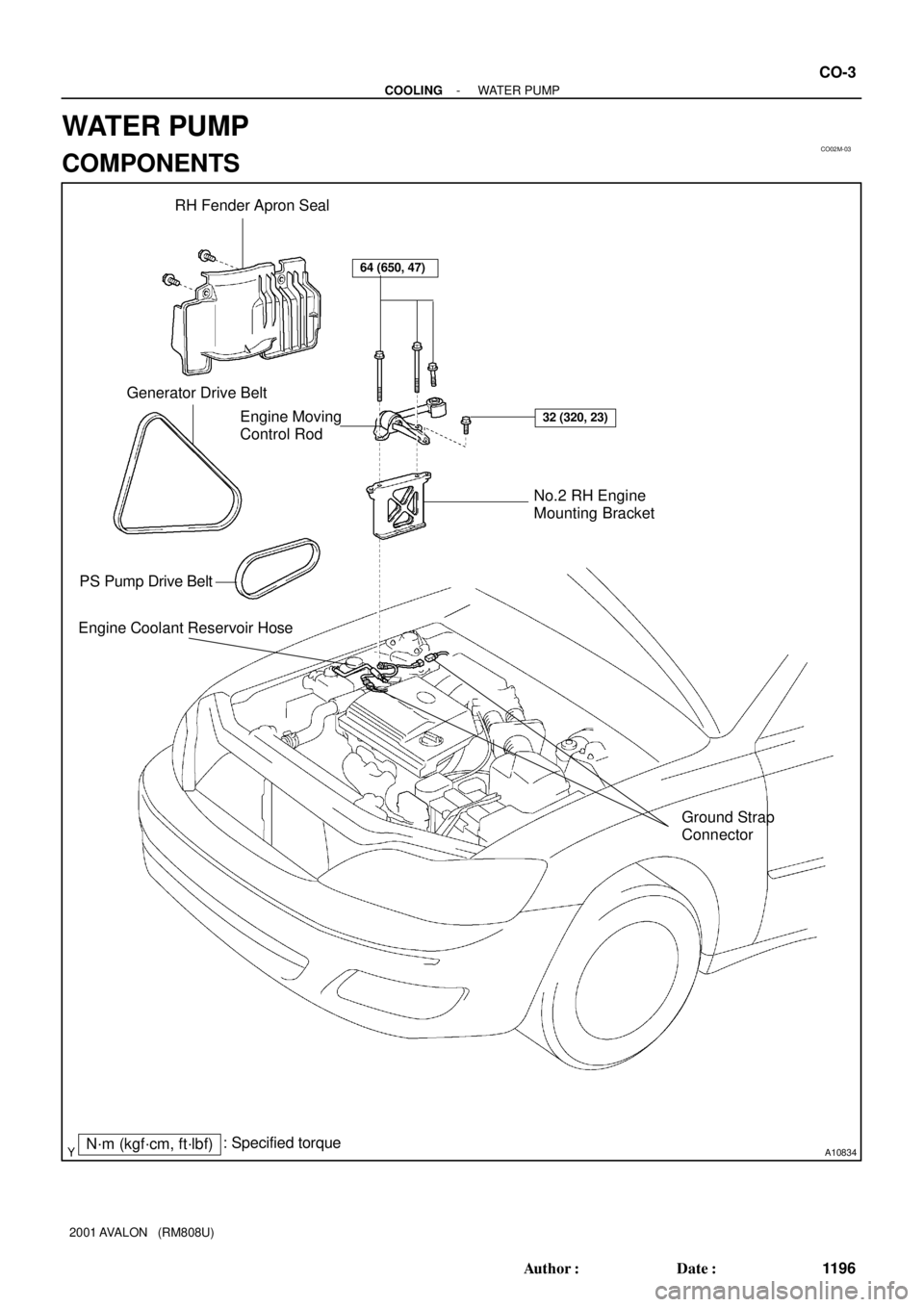
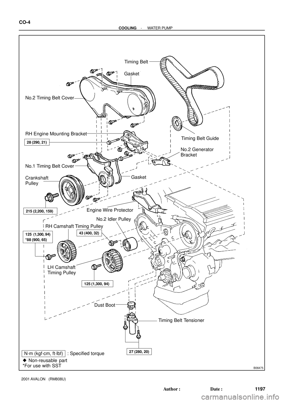
WATER PUMP
COMPONENTS
Page 593 of 1897
B06475
No.2 Timing Belt CoverTiming Belt
Gasket
Timing Belt Guide
No.2 Generator
Bracket RH Engine Mounting Bracket
28 (290, 21)
Crankshaft
Pulley
215 (2,200, 159)
Gasket
Engine Wire Protector
125 (1,300, 94)
*88 (900, 65)
RH Camshaft Timing Pulley
43 (400, 32)
No.2 Idler Pulley
125 (1,300, 94)
Dust Boot
Timing Belt Tensioner
27 (280, 20)
� Non-reusable part
*For use with SSTNo.1 Timing Belt Cover
LH Camshaft
Timing Pulley
N´m (kgf´cm, ft´lbf) : Specified torque
CO-4
- COOLINGWATER PUMP
1197 Author�: Date�:
2001 AVALON (RM808U)
Page 839 of 1897
- DIAGNOSTICSBODY CONTROL SYSTEM
DI-623
779 Author�: Date�:
2001 AVALON (RM808U)
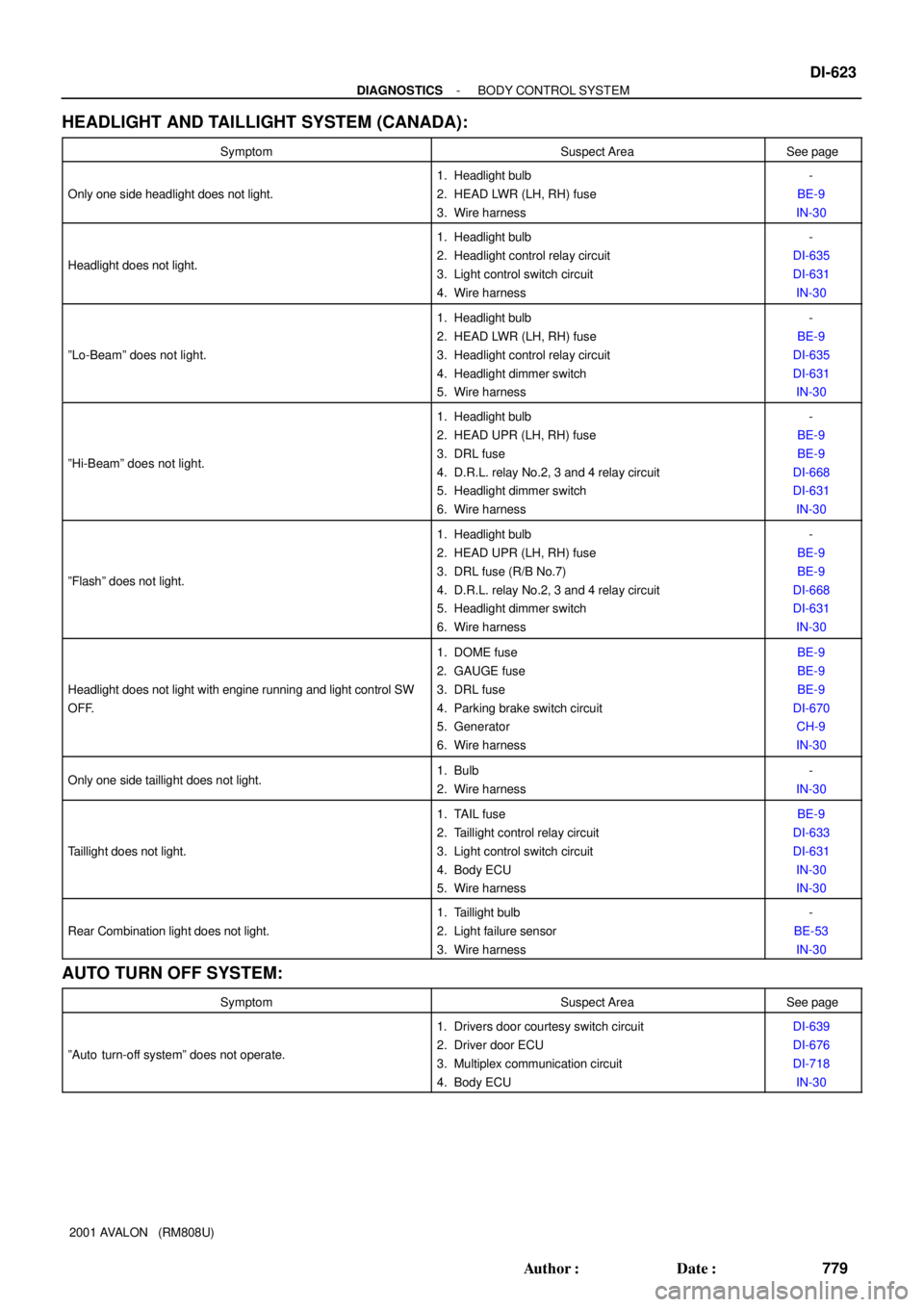
HEADLIGHT AND TAILLIGHT SYSTEM (CANADA):
SymptomSuspect AreaSee page
Only one side headlight does not light.
1. Headlight bulb
2. HEAD LWR (LH, RH) fuse
3. Wire harness-
BE-9
IN-30
Headlight does not light.
1. Headlight bulb
2. Headlight control relay circuit
3. Light control switch circuit
4. Wire harness-
DI-635
DI-631
IN-30
ºLo-Beamº does not light.
1. Headlight bulb
2. HEAD LWR (LH, RH) fuse
3. Headlight control relay circuit
4. Headlight dimmer switch
5. Wire harness-
BE-9
DI-635
DI-631
IN-30
ºHi-Beamº does not light.
1. Headlight bulb
2. HEAD UPR (LH, RH) fuse
3. DRL fuse
4. D.R.L. relay No.2, 3 and 4 relay circuit
5. Headlight dimmer switch
6. Wire harness-
BE-9
BE-9
DI-668
DI-631
IN-30
ºFlashº does not light.
1. Headlight bulb
2. HEAD UPR (LH, RH) fuse
3. DRL fuse (R/B No.7)
4. D.R.L. relay No.2, 3 and 4 relay circuit
5. Headlight dimmer switch
6. Wire harness-
BE-9
BE-9
DI-668
DI-631
IN-30
Headlight does not light with engine running and light control SW
OFF.
1. DOME fuse
2. GAUGE fuse
3. DRL fuse
4. Parking brake switch circuit
5. Generator
6. Wire harnessBE-9
BE-9
BE-9
DI-670
CH-9
IN-30
Only one side taillight does not light.1. Bulb
2. Wire harness-
IN-30
Taillight does not light.
1. TAIL fuse
2. Taillight control relay circuit
3. Light control switch circuit
4. Body ECU
5. Wire harnessBE-9
DI-633
DI-631
IN-30
IN-30
Rear Combination light does not light.
1. Taillight bulb
2. Light failure sensor
3. Wire harness-
BE-53
IN-30
AUTO TURN OFF SYSTEM:
SymptomSuspect AreaSee page
ºAuto turn-off systemº does not operate.
1. Drivers door courtesy switch circuit
2. Driver door ECU
3. Multiplex communication circuit
4. Body ECUDI-639
DI-676
DI-718
IN-30