Page 50 of 1897

AC1N4-02
N20259
(A)
(B)
AC-50
- AIR CONDITIONINGCOMPRESSOR AND MAGNETIC CLUTCH
1972 Author�: Date�:
2001 AVALON (RM808U)
INSTALLATION
1. INSTALL COMPRESSOR
(a) Install the compressor with 3 nuts.
Torque: 25 N´m (250 kgf´cm, 18 ft´lbf)
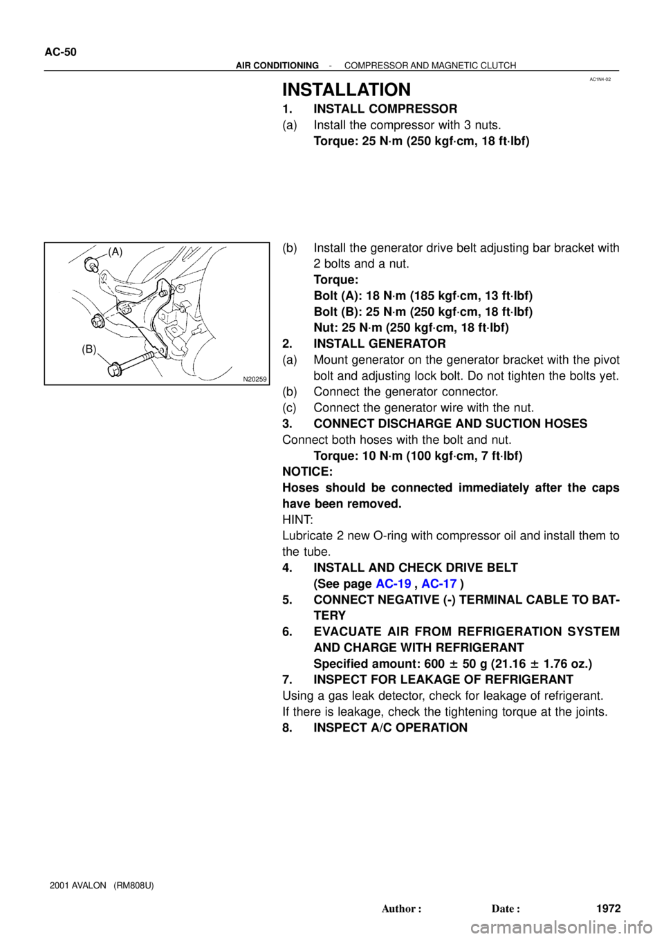
(b) Install the generator drive belt adjusting bar bracket with
2 bolts and a nut.
Torque:
Bolt (A): 18 N´m (185 kgf´cm, 13 ft´lbf)
Bolt (B): 25 N´m (250 kgf´cm, 18 ft´lbf)
Nut: 25 N´m (250 kgf´cm, 18 ft´lbf)
2. INSTALL GENERATOR
(a) Mount generator on the generator bracket with the pivot
bolt and adjusting lock bolt. Do not tighten the bolts yet.
(b) Connect the generator connector.
(c) Connect the generator wire with the nut.
3. CONNECT DISCHARGE AND SUCTION HOSES
Connect both hoses with the bolt and nut.
Torque: 10 N´m (100 kgf´cm, 7 ft´lbf)
NOTICE:
Hoses should be connected immediately after the caps
have been removed.
HINT:
Lubricate 2 new O-ring with compressor oil and install them to
the tube.
4. INSTALL AND CHECK DRIVE BELT
(See page AC-19, AC-17)
5. CONNECT NEGATIVE (-) TERMINAL CABLE TO BAT-
TERY
6. EVACUATE AIR FROM REFRIGERATION SYSTEM
AND CHARGE WITH REFRIGERANT
Specified amount: 600 ± 50 g (21.16 ± 1.76 oz.)
7. INSPECT FOR LEAKAGE OF REFRIGERANT
Using a gas leak detector, check for leakage of refrigerant.
If there is leakage, check the tightening torque at the joints.
8. INSPECT A/C OPERATION
Page 53 of 1897
AC1N1-02
I12935
P19978
N20259
AC-44
- AIR CONDITIONINGCOMPRESSOR AND MAGNETIC CLUTCH
1966 Author�: Date�:
2001 AVALON (RM808U)
REMOVAL
1. RUN ENGINE AT IDLE SPEED WITH A/C ON FOR
APPROX. 10 MINUTES
2. STOP ENGINE
3. DISCONNECT NEGATIVE (- ) TERMINAL CABLE
FROM BATTERY
4. DISCHARGE REFRIGERANT FROM REFRIGERATION
SYSTEM
5. REMOVE DRIVE BELT
(See page AC-18)
6. DISCONNECT DISCHARGE AND SUCTION HOSES
Remove the 2 nuts and disconnect the both hoses.
NOTICE:
Cap the open fittings immediately to keep moisture or dirt
out of the system.
7. REMOVE GENERATOR
(a) Disconnect the generator connector.
(b) Remove the nut, and disconnect the generator wire.
(c) Disconnect the wire harness from the clamp.
(d) Remove the pivot bolt, adjusting lock bolt and generator.
8. REMOVE COMPRESSOR
(a) Disconnect the connector.
(b) Disconnect the wire harness clamp.
(c) Remove the 2 bolts, nut and drive belt adjusting bar
bracket.
Page 63 of 1897
AC2FW-01
P00763
Pivot Bolt
Adjusting Lock Bolt
- AIR CONDITIONINGDRIVE BELT
AC-19
1941 Author�: Date�:
2001 AVALON (RM808U)
INSTALLATION
INSTALL DRIVE BELT
(a) Install the drive belt.
(b) Apply drive belt tension by adjusting bolt.
Drive belt tension:
New belt: 165 ± 22 lbf
Used belt: 110 ± 22 lbf
(c) Tighten the adjusting lock bolt and pivot bolt.
Torque:
Pivot bolt: 56 N´m (570 kgf´cm, 41 ft´lbf)
Adjusting lock bolt: 18 N´m (185 kgf´cm, 13 ft´lbf)
Page 65 of 1897
AC0YG-03
P00763
Pivot Bolt
Adjusting Lock Bolt
AC-18
- AIR CONDITIONINGDRIVE BELT
1940 Author�: Date�:
2001 AVALON (RM808U)
REMOVAL
REMOVE DRIVE BELT
(a) Loosen the pivot bolt and adjusting lock nut.
(b) Loosen the drive belt tension by adjusting bolt and re-
move the drive belt.
Page 553 of 1897
CH03V-02
B09070
Pivot Bolt
Plate Washer
Adjusting Lock BoltAdjusting Bolt
GeneratorGenerator Wire
Generator Connector
Drive Belt
Wire Clamp
Wire Clamp
B09071
PulleyDrive End Flame (Stator)� Front BearingRetainer
RotorBearing Cover
� Rear Bearing Bearing Cover
Thrust Washer
Rectifire End FlameCord ClipSeal Plate
Robber InsulatorRectifire Holder Terminal Insulator
Voltage RegulatorBrush Holder Brush Holder CoverRear End CoverPlate Terminal
� Non-reusable part
x 4
x 4
- CHARGINGGENERATOR
CH-5
1278 Author�: Date�:
2001 AVALON (RM808U)
GENERATOR
COMPONENTS
Page 562 of 1897
CH03W-02
P19938
P19978
CH-6
- CHARGINGGENERATOR
1279 Author�: Date�:
2001 AVALON (RM808U)
REMOVAL
1. REMOVE DRIVE BELT
Loosen the pivot bolt, adjusting lock bolt and adjusting bolt, and
remove the drive belt.
Torque:
Lock bolt: 18 N´m (180 kgf´cm, 13 ft´lbf)
Pivot bolt: 56 N´m (570 kgf´cm, 41 ft´lbf)
2. REMOVE GENERATOR
(a) Disconnect the generator connector.
(b) Remove the nut, and disconnect the generator wire.
Torque: 9.8 N´m (100 kgf´cm, 86 in.´lbf)
(c) Disconnect the wire harness from the clip.
(d) Remove the pivot bolt, plate washer, adjusting lock bolt
and generator.
Page 670 of 1897

F07893
DI-288
- DIAGNOSTICSABS WITH EBD & BA & TRAC & VSC SYSTEM
444 Author�: Date�:
2001 AVALON (RM808U)
INSPECTION PROCEDURE
HINT:
Start the inspection from step 1 in case of using the TOYOTA hand-held tester and start from step 2 in case
of not using the TOYOTA hand-held tester.
1 Check output value of the yaw rate sensor.
PREPARATION:
(a) Remove the 2 bolts and yaw rate sensor with connector
still connected.
(b) Connect the TOYOTA hand-held tester to the DLC3.
(c) Turn the ignition switch ON and push the TOYOTA hand-
held tester main switch ON.
(d) Select the DATALIST mode on the TOYOTA hand-held
tester.
CHECK:
Check that the yaw rate value of the yaw rate sensor displayed
on the TOYOTA hand-held tester is changing: Place the yaw
rate sensor vertically to the ground and turn the sensor pivoted
on its center.
OK:
Yaw rate value must be changing.
OK Go to step 3.
NG
2 Check whether continuity exists between terminal YD of yaw rate sensor and ter-
minal YD of ABS & BA & TRAC & VSC ECU.
NG Repair or replace harness or connector.
OK
Check and replace ABS & BA & TRAC & VSC
ECU.
Page 1381 of 1897

EM0ZD-02
A05060
Inward
Sensor
A01802
10 mm
Hexagon
Wrench
Plate Washer
A05055
A05061
Fulcrum
Length
SSTSST
RH
- ENGINE MECHANICALTIMING BELT
EM-21
1005 Author�: Date�:
2001 AVALON (RM808U)
INSTALLATION
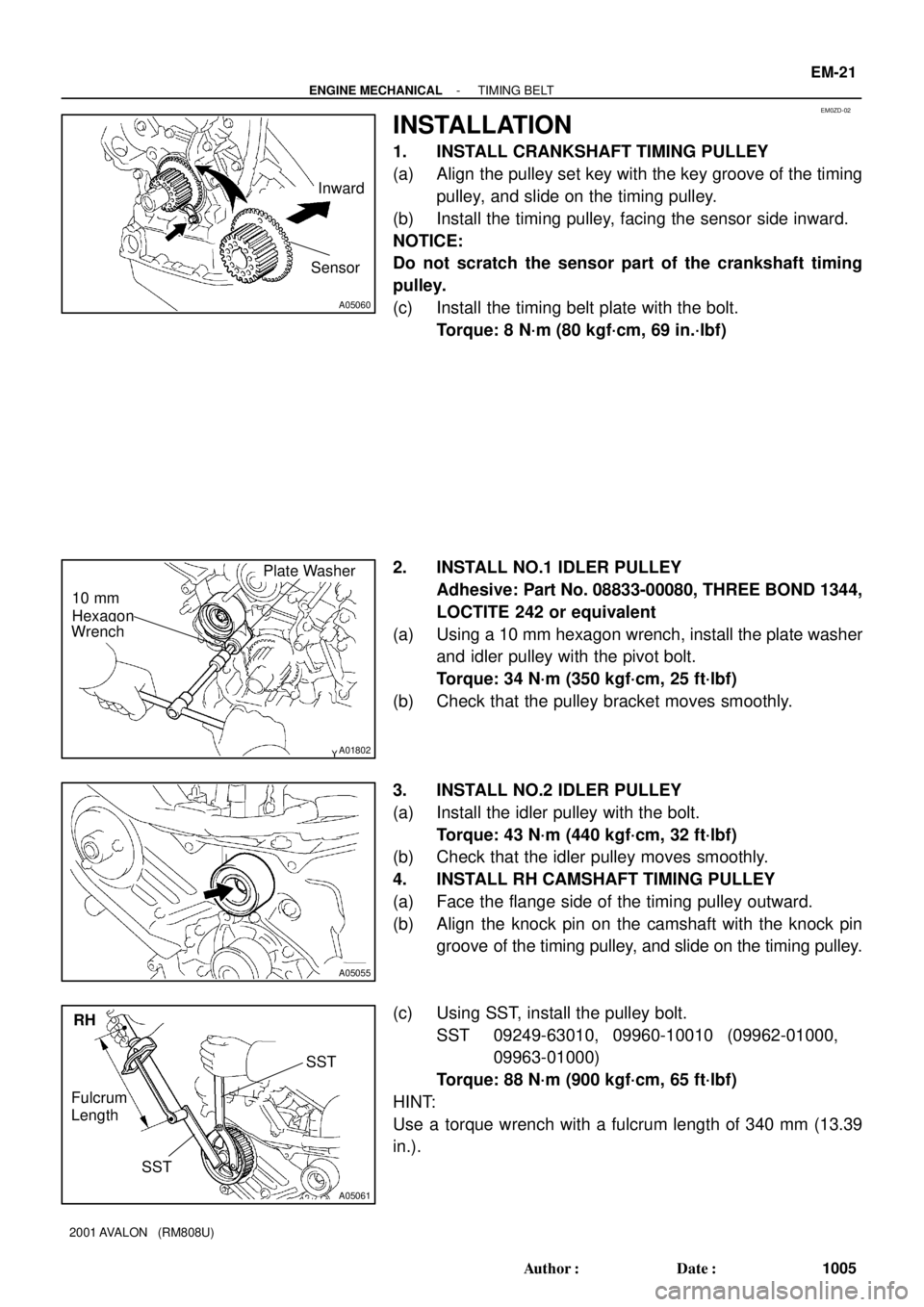
1. INSTALL CRANKSHAFT TIMING PULLEY
(a) Align the pulley set key with the key groove of the timing
pulley, and slide on the timing pulley.
(b) Install the timing pulley, facing the sensor side inward.
NOTICE:
Do not scratch the sensor part of the crankshaft timing
pulley.
(c) Install the timing belt plate with the bolt.
Torque: 8 N´m (80 kgf´cm, 69 in.´lbf)
2. INSTALL NO.1 IDLER PULLEY
Adhesive: Part No. 08833-00080, THREE BOND 1344,
LOCTITE 242 or equivalent
(a) Using a 10 mm hexagon wrench, install the plate washer
and idler pulley with the pivot bolt.
Torque: 34 N´m (350 kgf´cm, 25 ft´lbf)
(b) Check that the pulley bracket moves smoothly.
3. INSTALL NO.2 IDLER PULLEY
(a) Install the idler pulley with the bolt.
Torque: 43 N´m (440 kgf´cm, 32 ft´lbf)
(b) Check that the idler pulley moves smoothly.
4. INSTALL RH CAMSHAFT TIMING PULLEY
(a) Face the flange side of the timing pulley outward.
(b) Align the knock pin on the camshaft with the knock pin
groove of the timing pulley, and slide on the timing pulley.
(c) Using SST, install the pulley bolt.
SST 09249-63010, 09960-10010 (09962-01000,
09963-01000)
Torque: 88 N´m (900 kgf´cm, 65 ft´lbf)
HINT:
Use a torque wrench with a fulcrum length of 340 mm (13.39
in.).