Page 1576 of 1897

SUSPENSION AND AXLE
SERVICE DATA
Cold tire inflation
pressureP205/65R15 92H Front, rear
P205/60R16")
SS04W-07
- SERVICE SPECIFICATIONSSUSPENSION AND AXLE
SS-27
143 Author�: Date�:
2001 AVALON (RM808U)
SUSPENSION AND AXLE
SERVICE DATA
Cold tire inflation
pressureP205/65R15 92H Front, rear
P205/60R16 91H Front, rear210 kPa (2.1 kgf/cm2, 31 psi)
220 kPa (2.2 kgf/cm2, 32 psi)
Vehicle heightFront*1
Rear*2213 mm (8.39 in.)
266 mm (10.47 in.)
Camber
Right-left error-0°37' ± 45' (-0.62° ± 0.75°)
45' (0.75°) or less
Front Wheel
Caster
Right-left error2°10' ± 45' (2.17° ± 0.75°)
45' (0.75°) or less
Front Wheel
alignmentSteering axis inclination
Right-left error13°04' ± 45' (13.07° ± 0.75°)
45' (0.75°) or less
Toe-in (total)
Rack end length difference0° ± 12' (0° ± 0.2°, 0 ± 2 mm, 0 ± 0.08 in.)
1.5 mm (0.059 in.) or less
Wheel angle Inside wheel
Outside wheel: Reference35°45' ± 1° (35.75° ± 1°)
31°23' (31.38°)
Rear wheel
Camber
Right-left error-0°43' ± 45' (-0.72° ± 0.75°)
45' (0.75°) or less
Rear wheel
alignmentToe-in (total)
No. 2 lower suspension arm length difference0°24' ± 12' (0.4° ± 0.2°, 4 ± 2 mm, 0.16 ± 0.08 in.)
1 mm (0.04 in.) or less
FtlAxle bearing backlash Maximum0.05 mm (0.0020 in.)Front axleAxle hub deviationMaximum0.05 mm (0.0020 in.)
Front drive shaftDrive shaft standard length LH
RH586.0 ± 2.0 mm (23.071 ± 0.079 in.)
881.6 ± 2.0 mm (34.709 ± 0.079 in.)
Ft iLower ball joint turning torque1.0 - 3.4 N´m (10 - 35 kgf´cm, 8.7 - 30 in.´lbf)Front suspensionStabilizer bar link ball joint turning torque0.05 - 1.0 N´m (0.5 - 10 kgf´cm, 0.4 - 8.7 in.´lbf)
RlAxle bearing backlash Maximum0.05 mm (0.0020 in.)Rear axleAxle hub deviationMaximum0.07 mm (0.0028 in.)
RiNo. 2 lower suspension arm length512.3 mm (20.169 in.)Rear suspensionStabilizer bar link ball joint turning torque0.05 - 1.0 N´m (0.5 - 10 kgf´cm, 0.4 - 8.7 in.´lbf)
*1: Front measuring point
Measure the distance from the ground to the center of the front side lower suspension arm mounting bolt.
*2: Rear measuring point
Measure the distance from the ground to the center of the front side strut rod mounting bolt.
Page 1581 of 1897

STEERING
SERVICE DATA
DRIVE BELT
Drive belt tension* New belt120 - 185 lbf
Drive belt tension* Used belt9")
SS0G9-03
SS-32
- SERVICE SPECIFICATIONSSTEERING
148 Author�: Date�:
2001 AVALON (RM808U)
STEERING
SERVICE DATA
DRIVE BELT
Drive belt tension* New belt120 - 185 lbf
Drive belt tension* Used belt95 - 135 lbf
POWER STEERING FLUID
Fluid level rise Maximum5 mm (0.20 in.)
Fluid pressure at idle speed with valve closed Minimum7,845 kPa (80 kgf/cm2, 1,138 psi)
STEERING WHEEL
Steering wheel freeplayMaximum30 mm (1.18 in.)
Steering effort at idle speedReference5.9 N´m (60 kgf´cm, 52 in.´lbf)
POWER STEERING VANE PUMP
Vane pump rotating torque0.3 N´m (2.8 kgf´cm, 2.4 in.´lbf) or less
Oil clearance between pump shaft and bushing STD0.03 - 0.05 mm (0.0012 - 0.0020 in.)
Oil clearance between pump shaft and bushingMaximum0.07 mm (0.0028 in.)
Vane plate heightMinimum8.6 mm (0.339 in.)
Vane plate thickness Minimum1.397 mm (0.0550 in.)
Vane plate lengthMinimum14.991 mm (0.5902 in.)
Clearance between the rotor groove and plateMaximum0.035 mm (0.0014 in.)
Vane plate length Pump rotor and cam ring mark
None14.999 - 15.001 mm (0.59051 - 0.59059 in.)
114.997 - 14.999 mm (0.59043 - 0.59051 in.)
214.995 - 14.997 mm (0.59035 - 0.59043 in.)
314.993 - 14.995 mm (0.59027 - 0.59035 in.)
414.991 - 14.993 mm (0.59020 - 0.59027 in.)
Spring free length Minimum32.3 mm (1.272 in.)
POWER STEERING GEAR
Steering rack runout Maximum0.03 mm (0.0012 in.)
Total preload (Control valve rotating torque)0.8 - 1.4 N´m (8 - 14 kgf´cm, 6.9 - 12.2 in.´lbf)
*: For use with belt tension gauge
Page 1582 of 1897

TORQUE SPECIFICATION
Part tightenedN´mkgf´cmft´lbf
TILT STEERING COLUMN
Tilt lever lock shaft9.09078 in.")
SS0GA-06
- SERVICE SPECIFICATIONSSTEERING
SS-33
149 Author�: Date�:
2001 AVALON (RM808U)
TORQUE SPECIFICATION
Part tightenedN´mkgf´cmft´lbf
TILT STEERING COLUMN
Tilt lever lock shaft9.09078 in.´lbf
Turn signal bracket x Steering column upper tube7.57565 in.´lbf
Shift lever housing x Column tube assembly101007
Shift lever set bolt1111 08
Shift lock solenoid bracket x Shift lever housing3.43530 in.´lbf
Shift lock switch guide2.82925 in.´lbf
Universal joint assembly x Main shaft assembly3536026
Steering column assembly set nut2526019
Intermediate shaft sub-assembly x Control valve shaft3536026
Universal joint assembly x Intermediate shaft sub-assembly3536026
Steering wheel set nut5051037
Steering wheel pad set screw (Torx screw)8.89078 in.´lbf
POWER STEERING VANE PUMP
Rear housing set bolt1717012
Pressure port union8385062
Suction port union set bolt131309
Front bracket x Rear bracket4344032
Vane pump pulley set nut4445033
Pressure feed tube x PS vane pump assembly5253038
Oil pressure switch2121015
PS vane pump set bolt A bolt29 (43)300 (440)22 (32)
PS vane pump set bolt B bolt4344032
Pressure feed tube x Pressure feed tube23 (25)230 (250)17 (18)
Clamp plate set nut7.88069 in.´lbf
POWER STEERING GEAR
Control valve housing set bolt1818013
Self-locking nut2525018
Rack housing cap5960043
Rack guide spring cap lock nut50 (69)510 (700)37 (51)
Rack x Rack end60 (83)610 (850)45 (61)
Tie rod end lock nut7475054
Turn pressure tube union nut12 (13)120 (130)9 (9)
PS gear assembly set bolt1811,850134
Stabilizer bar set bolt1919014
Pressure feed and return tubes x Control valve housing28 (25)290 (250)21 (18)
Pressure feed tube clamp plate set nut101007
Intermediate shaft sub-assembly x Control valve shaft3536026
Tie rod end x Steering knuckle4950036
( ): For use without SST
Page 1739 of 1897
RS00Y-47
H11885
Column Upper Cover
Spiral Cable
Steering Wheel
Steering Wheel Pad
Column Lower Cover
N´m (kgf´cm, ft´lbf) : Specified torque
8.8 (90, 78 in.´lbf)
50 (510, 37)
Steering Wheel Lower
No. 2 CoverSteering Wheel Lower
No. 2 Cover
Torx Screw
- SUPPLEMENTAL RESTRAINT SYSTEMSTEERING WHEEL PAD AND SPIRAL CABLE
RS-13
1533 Author�: Date�:
2001 AVALON (RM808U)
STEERING WHEEL PAD AND SPIRAL CABLE
COMPONENTS
Page 1789 of 1897

INSTALLATION
1. INSTALL PS GEAR ASSEMBLY
(a) Install the PS gear assembly from the LH")
SR0EY-06
F13589
SST
Fulcrum Length
SR-56
- STEERINGPOWER STEERING GEAR
1519 Author�: Date�:
2001 AVALON (RM808U)
INSTALLATION
1. INSTALL PS GEAR ASSEMBLY
(a) Install the PS gear assembly from the LH of the vehicle.
NOTICE:
Do not damage the turn pressure tubes.
(b) Install the 2 gear assembly set bolts and nuts.
Torque: 181 N´m (1,850 kgf´cm, 134 ft´lbf)
HINT:
Lift up the stabilizer bar and install the bolts.
2. INSTALL NO. 1 FUEL TUBE PROTECTOR
Install the No. 1 fuel tube protector with 2 bolts and nut.
3. CONNECT STABILIZER BAR
Connect the stabilizer bar with the 4 bolts.
Torque: 19 N´m (190 kgf´cm, 14 ft´lbf)
4. CONNECT PRESSURE FEED AND RETURN TUBES
(a) Coat 2 new O-rings with power steering fluid and install
them to the pressure feed and return tubes.
(b) Using SST, connect the pressure feed and return tubes.
SST 09023-38400
Torque: 28 N´m (290 kgf´cm, 21 ft´lbf)
HINT:
�Use a torque wrench with a fulcrum length of 300 mm
(11.81 in.).
�This torque value is effective in case that SST is parallel
to a torque wrench.
5. CONNECT CLAMP PLATE
Connect the clamp plate with nut.
Torque: 10 N´m (100 kgf´cm, 7 ft´lbf)
6. CONNECT INTERMEDIATE SHAFT SUB-ASSEMBLY
(See page SR-22)
7. CONNECT RH AND LH TIE ROD ENDS
(See page SA-13)
8. PLACE FRONT WHEELS FACING STRAIGHT AHEAD
HINT:
Do it with the front of the vehicle jacked up.
9. CENTER SPIRAL CABLE (See page SR-22)
10. INSTALL STEERING WHEEL
(a) Align the matchmarks on the steering wheel and steering
column main shaft.
(b) Temporarily tighten the steering wheel set nut.
(c) Connect the connector.
11. BLEED POWER STEERING SYSTEM
(See page SR-4)
Page 1790 of 1897
- STEERINGPOWER STEERING GEAR
SR-57
1520 Author�: Date�:
2001 AVALON (RM808U)
12. CHECK STEERING WHEEL CENTER POINT
13. TORQUE STEERING WHEEL SET NUT
Torque: 50 N´m (510 kgf´cm, 37 ft´lbf)
14. INSTALL STEERING WHEEL PAD (See page SR-22)
15. CHECK FRONT WHEEL ALIGNMENT
(See page SA-4)
16. w/ VSC:
PERFORM STEERING ANGLE SENSOR ZERO POINT
CALIBRATION (See page DI-252)
Page 1796 of 1897

or less
SST
R00429
Matchmarks SR-54
- STEERINGPOWER STEERING GEAR
1517 Author�: Date�:
2001 AVALON (RM808U)
(c) Using a brass bar and hammer, stake the")
R11668
Brass Bar
R11669
W04223
2 mm
(0.79 in.)
or less
SST
R00429
Matchmarks SR-54
- STEERINGPOWER STEERING GEAR
1517 Author�: Date�:
2001 AVALON (RM808U)
(c) Using a brass bar and hammer, stake the claw washer.
NOTICE:
Avoid any impact on the steering rack.
(d) Employ the same manner described above to the other
side.
18. INSTALL RH AND LH RACK BOOTS, CLAMPS AND
CLIPS
(a) Ensure that the steering rack hole is not clogged with
grease.
HINT:
If the hole is clogged, the pressure inside the rack boot will
change after it is assembled and the steering wheel is turned.
(b) Install the rack boot, clip and a new clamp.
NOTICE:
Be careful not to damage or twist the rack boot.
(c) Using SST, tighten the clamp as shown in the illustration.
SST 09521-24010
(d) Employ the same manner described above to the other
side.
19. INSTALL RH AND LH TIE ROD ENDS AND LOCK NUTS
(a) Screw the lock nut and tie rod end onto the rack end until
the matchmarks are aligned.
(b) After adjusting toe-in, torque the lock nut (See page
SA-4).
Torque: 74 N´m (750 kgf´cm, 54 ft´lbf)
(c) Employ the same manner described above to the other
side.
Page 1815 of 1897
F08857
SR0EG-05
F08858
SR-8
- STEERINGSTEERING WHEEL
1471 Author�: Date�:
2001 AVALON (RM808U)
STEERING WHEEL
INSPECTION
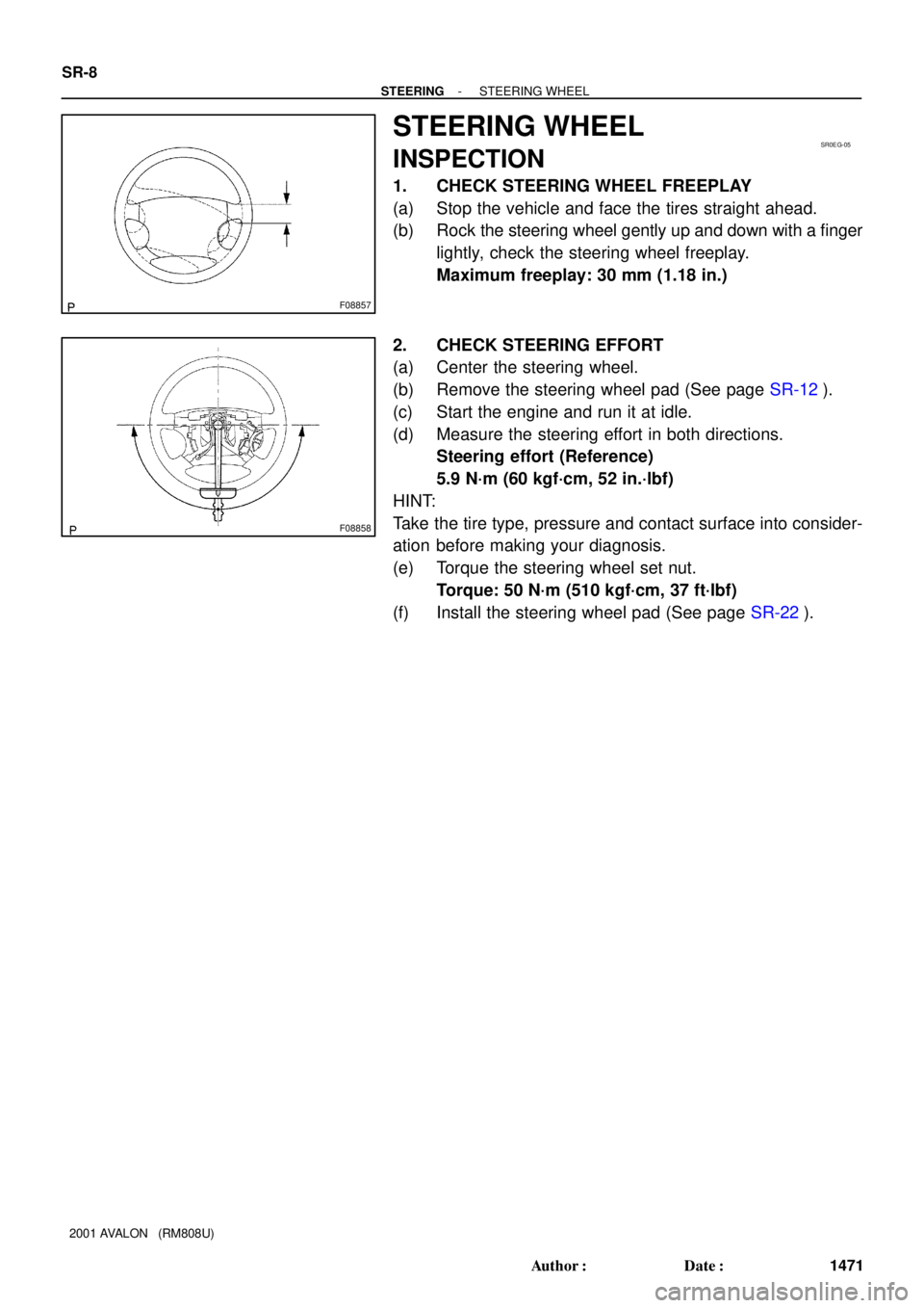
1. CHECK STEERING WHEEL FREEPLAY
(a) Stop the vehicle and face the tires straight ahead.
(b) Rock the steering wheel gently up and down with a finger
lightly, check the steering wheel freeplay.
Maximum freeplay: 30 mm (1.18 in.)
2. CHECK STEERING EFFORT
(a) Center the steering wheel.
(b) Remove the steering wheel pad (See page SR-12).
(c) Start the engine and run it at idle.
(d) Measure the steering effort in both directions.
Steering effort (Reference)
5.9 N´m (60 kgf´cm, 52 in.´lbf)
HINT:
Take the tire type, pressure and contact surface into consider-
ation before making your diagnosis.
(e) Torque the steering wheel set nut.
Torque: 50 N´m (510 kgf´cm, 37 ft´lbf)
(f) Install the steering wheel pad (See page SR-22).
 : Specified torque
8.8 (90, 78 in.´lbf)
50 (510, 37)
Steering Wheel Lower")