Page 1863 of 1897

REMOVAL
1. REMOVE FRONT WHEEL
Torque: 103 N´m (1,050 kgf´cm, 76 ft´lbf)
2. DIS")
SA0V0-02
F07388
To outside SA-26
- SUSPENSION AND AXLEFRONT SHOCK ABSORBER
1360 Author�: Date�:
2001 AVALON (RM808U)
REMOVAL
1. REMOVE FRONT WHEEL
Torque: 103 N´m (1,050 kgf´cm, 76 ft´lbf)
2. DISCONNECT FLEXIBLE HOSE AND ABS SPEED
SENSOR WIRE HARNESS CLAMP
Remove the bolt and disconnect the flexible hose and ABS
speed sensor wire harness clamp from the shock absorber.
Torque: 29 N´m (300 kgf´cm, 22 ft´lbf)
3. DISCONNECT STABILIZER BAR LINK FROM SHOCK
ABSORBER (See page SA-41)
4. DISCONNECT SHOCK ABSORBER FROM STEERING
KNUCKLE
(a) Remove the 2 nuts and bolts on the lower side of the
shock absorber.
Torque: 211 N´m (2,150 kgf´cm, 156 ft´lbf)
(b) Remove the shock absorber from the steering knuckle.
HINT:
At the time of installation, coat the nut's threads with engine oil.
5. REMOVE SHOCK ABSORBER WITH COIL SPRING
Remove the 3 nuts and shock absorber with the coil spring.
Torque: 80 N´m (820 kgf´cm, 59 ft´lbf)
HINT:
At the time of installation, rotate the suspension support and set
it in the direction, as shown.
Page 1867 of 1897
SA0W3-02
F06454
F06456
- SUSPENSION AND AXLEFRONT STABILIZER BAR
SA-41
1375 Author�: Date�:
2001 AVALON (RM808U)
REMOVAL
1. REMOVE FRONT WHEELS
Torque: 103 N´m (1,050 kgf´cm, 76 ft´lbf)
2. REMOVE STABILIZER BAR LINKS
(a) Remove the 2 nuts and stabilizer bar link.
Torque: 39 N´m (400 kgf´cm, 29 ft´lbf)
HINT:
If the ball joint turns together with the nut, use a hexagon (5 mm)
wrench to hold the stud.
(b) Employ the same manner described above to the other
side.
3. REMOVE BRACKETS AND BUSHINGS
(a) Remove the 2 bolts, bracket and bushing.
Torque: 19 N´m (195 kgf´cm, 14 ft´lbf)
HINT:
At the time of installation, install the bushing to the inside of the
bushing stopper on the stabilizer bar.
(b) Employ the same manner described above to the other
side.
4. REMOVE STABILIZER BAR
Remove the stabilizer bar from the left hand side.
NOTICE:
Be careful not to damage the pressure feed tube.
Page 1869 of 1897

F04031
F04048
1
2
F01195
Bolt
Adjusting
ValueSet Bolt
15'
30'Adjusting Bolt90105-17001 90105-17003 90105-17004 90105-17005
45'
1°00'
1°15'
1°30'121212121 Dot
2 Dots3 Dots
- SUSPENSION AND AXLEFRONT WHEEL ALIGNMENT
SA-5
1339 Author�: Date�:
2001 AVALON (RM808U)
4. ADJUST CAMBER
NOTICE:
After the camber has been adjusted, inspect the toe-in.
(a) Remove the front wheel and ABS speed sensor clamp.
(b) Remove the 2 nuts on the lower side of the shock absorb-
er.
(c) Coat the threads of the nuts with engine oil.
(d) Temporarily install the 2 nuts.
(e) Adjust the camber by pushing or pulling the lower side of
the shock absorber in the direction in which the camber
adjustment is required.
(f) Tighten the nuts.
Torque: 211 N´m (2,150 kgf´cm, 156 ft´lbf)
(g) Install the ABS speed sensor clamp and front wheel.
Torque: 103 N´m (1,050 kgf´cm, 76 ft´lbf)
(h) Check the camber.
HINT:
�Try to adjust the camber to the center of the specified val-
ue.
�Adjusting value for the set bolts is 6' - 30' (0.1° - 0.5°).
If the camber is not within the specified value, using the follow-
ing table, estimate how much additional camber adjustment will
be required, and select the camber adjusting bolt.
(i) Do the steps mentioned above again. Between step (b)
and (c), replace 1 or 2 selected bolts.
HINT:
When replacing the 2 bolts, replace 1 bolt for each time.
Page 1870 of 1897

5. INSPECT TOE-IN
Toe-in:
Toe-in")
SA3213
Front A
DB
C
F02245
F02246
SA0028
Front AB
A B
A: Inside
B: Outside SA-6
- SUSPENSION AND AXLEFRONT WHEEL ALIGNMENT
1340 Author�: Date�:
2001 AVALON (RM808U)
5. INSPECT TOE-IN
Toe-in:
Toe-in
(total)A + B: 0° ± 12' (0° ± 0.2°)
C - D: 0 ± 2 mm (0 ± 0.08 in.)
If the toe-in is not within the specified value, adjust it at the rack
ends.
6. ADJUST TOE-IN
(a) Remove the rack boot set clips.
(b) Loosen the tie rod end lock nuts.
(c) Turn the right and left rack ends by an equal amount to
adjust the toe-in.
HINT:
Try to adjust the toe-in to the center of the specified value.
(d) Make sure that the lengths of the right and left rack ends
are the same.
Rack end length difference: 1.5 mm (0.059 in.) or less
(e) Torque the tie rod end lock nuts.
Torque: 74 N´m (750 kgf´cm, 54 ft´lbf)
(f) Place the boots on the seats and install the clips.
HINT:
Make sure that the boots are not twisted.
7. INSPECT WHEEL ANGLE
Turn the steering wheel fully, and measure the turning angle.
Wheel turning angle:
Inside wheel35°45' ± 1° (35.75° ± 1°)
Outside wheel: Reference31°23' (31.38°)
If the right and left inside wheel angles differ from the specified
value, check the right and left rack end lengths.
Page 1871 of 1897
SA0VW-02
W03096
SST
W03097
WasherNut SA-14
- SUSPENSION AND AXLEFRONT WHEEL HUB BOLT
1348 Author�: Date�:
2001 AVALON (RM808U)
FRONT WHEEL HUB BOLT
REPLACEMENT
1. REMOVE FRONT WHEEL
2. REMOVE BRAKE CALIPER AND DISC
(a) Remove the 2 bolts, brake caliper and disc.
(b) Support the brake caliper securely.
3. REMOVE HUB BOLT
Using SST and a hammer handle or an equivalent, remove the
hub bolt.
SST 09628-1001 1
4. INSTALL HUB BOLT
(a) Install a washer and nut to a new hub bolt, as shown in the
illustration.
(b) Using a hammer handle or an equivalent to hold, install
the hub bolt by torquing the nut.
5. INSTALL DISC AND BRAKE CALIPER
Install the disc and brake caliper with the 2 bolts.
Torque: 107 N´m (1,090 kgf´cm, 79 ft´lbf)
6. INSTALL FRONT WHEEL
Torque: 103 N´m (1,050 kgf´cm, 76 ft´lbf)
Page 1874 of 1897

REMOVAL
1. REMOVE REAR WHEEL
Torque: 103 N´m (1,050 kgf´cm, 76 ft´lbf)
2. R")
SA0W6-02
R10948
Z00206
W03211
A
A
B
- SUSPENSION AND AXLEREAR AXLE HUB
SA-45
1379 Author�: Date�:
2001 AVALON (RM808U)
REMOVAL
1. REMOVE REAR WHEEL
Torque: 103 N´m (1,050 kgf´cm, 76 ft´lbf)
2. REMOVE BRAKE CALIPER AND DISC
(a) Remove the brake caliper and disc.
Torque: 47 N´m (475 kgf´cm, 34 ft´lbf)
(b) Support the brake caliper securely.
3. CHECK BEARING BACKLASH AND AXLE HUB DEVI-
ATION
(a) Using a dial indicator, check the backlash near the center
of the axle hub.
Maximum: 0.05 mm (0.0020 in.)
If the backlash exceeds the maximum, replace the axle hub.
(b) Using a dial indicator, check the deviation at the surface
of the axle hub outside the hub bolt.
Maximum: 0.07 mm (0.0028 in.)
If the deviation exceeds the maximum, replace the axle hub.
4. DISCONNECT ABS SPEED SENSOR
Remove the bolt and disconnect the ABS speed sensor.
Torque: 8.0 N´m (82 kgf´cm, 71 in.´lbf)
5. REMOVE REAR AXLE HUB
(a) Remove the 4 bolts and rear axle hub.
Torque: 80 N´m (820 kgf´cm, 59 ft´lbf)
(b) Remove the O-ring.
HINT:
At the time of installation, coat a new O-ring with MP grease.
(c) Support the backing plate securely.
6. REMOVE REAR AXLE CARRIER
(a) Loosen the 3 nuts.
Torque:
Nut A (Reused nut): 196 N´m (2,000 kgf´cm, 145 ft´lbf)
Nut A (New nut): 255 N´m (2,600 kgf´cm, 188 ft´lbf)
Nut B: 181 N´m (1,850 kgf´cm, 134 ft´lbf)
Page 1879 of 1897
SA1F9-02
F06460
W03223
AB
F06462
SA-60
- SUSPENSION AND AXLEREAR LOWER SUSPENSION ARM AND STRUT ROD
1394 Author�: Date�:
2001 AVALON (RM808U)
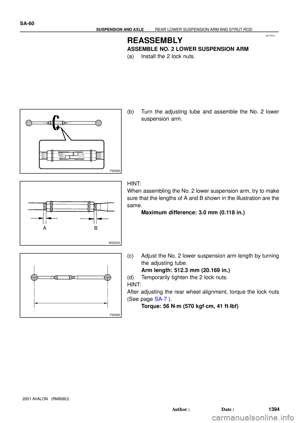
REASSEMBLY
ASSEMBLE NO. 2 LOWER SUSPENSION ARM
(a) Install the 2 lock nuts.
(b) Turn the adjusting tube and assemble the No. 2 lower
suspension arm.
HINT:
When assembling the No. 2 lower suspension arm, try to make
sure that the lengths of A and B shown in the illustration are the
same.
Maximum difference: 3.0 mm (0.118 in.)
(c) Adjust the No. 2 lower suspension arm length by turning
the adjusting tube.
Arm length: 512.3 mm (20.169 in.)
(d) Temporarily tighten the 2 lock nuts.
HINT:
After adjusting the rear wheel alignment, torque the lock nuts
(See page SA-7).
Torque: 56 N´m (570 kgf´cm, 41 ft´lbf)
Page 1880 of 1897

REMOVAL
1. REMOVE REAR WHEEL
Torque: 103 N´m (")
SA0VG-02
W03216
W03217
Rear
F06465A
A B
B
- SUSPENSION AND AXLEREAR LOWER SUSPENSION ARM AND STRUT ROD
SA-57
1391 Author�: Date�:
2001 AVALON (RM808U)
REMOVAL
1. REMOVE REAR WHEEL
Torque: 103 N´m (1,050 kgf´cm, 76 ft´lbf)
2. REMOVE CENTER EXHAUST PIPE
3. REMOVE STRUT ROD
(a) Remove the bolt and disconnect the parking brake cable.
Torque: 5.4 N´m (55 kgf´cm, 48 in.´lbf)
(b) Remove the 2 bolts and nuts.
Torque: 113 N´m (1,150 kgf´cm, 83 ft´lbf)
NOTICE:
Do not turn the nut.
HINT:
At the time of installation, after stabilizing the suspension,
torque the bolts.
(c) Remove the strut rod.
4. REMOVE NO. 2 LOWER SUSPENSION ARM
(a) Remove the 3 nuts, suspension arm washer and washer.
Torque: 181 N´m (1,850 kgf´cm, 134 ft´lbf)
HINT:
At the time of installation, after stabilizing the suspension,
torque the nuts.
(b) Remove the No. 2 lower suspension arm.
HINT:
At the time of installation, face the paint mark to the rearward.
5. REMOVE STABILIZER BAR BRACKETS
(See page SA-63)
6. REMOVE NO. 1 LOWER SUSPENSION ARM
(a) Support the suspension member with a jack.
(b) Remove the 4 nuts, 2 bolts and 8 suspension member
stoppers.
Torque:
A: 51 N´m (520 kgf´cm, 38 ft´lbf)
B: 38 N´m (390 kgf´cm, 28 ft´lbf)
(c) Lower the suspension member.