Page 2624 of 4770

439 Author�: Date�:
5 Check idle speed.
PREPARATION:
(a) Warm up the engine to normal operating temperature.
(b) Switch")
A00209
DLC1
TE1
E1
SST
DLC1
P12915
P12952
DI±204
± DIAGNOSTICSENGINE (1MZ±FE)
439 Author�: Date�:
5 Check idle speed.
PREPARATION:
(a) Warm up the engine to normal operating temperature.
(b) Switch off all accessories.
(c) Switch off air conditioning.
(d) Shift transmission into ºNº position.
(e) Connect the OBD II scan tool or TOYOTA hand±held tester to DLC3 on the vehicle.
CHECK:
Use CURRENT DATA to check the idle speed.
OK:
Idle speed: 650 ~ 750 rpm
NG Proceed to problem symptoms table on
page DI±221.
OK
6 Check ignition timing.
PREPARATION:
(a) Warm up the engine to normal operating temperature.
(b) Switch off all accessories.
(c) Switch off air conditioning.
(d) Shift transmission into ºNº position.
(e) Keep the engine speed at idle.
(f) Using SST, connect terminals TE1 and E1 of the DLC1.
SST 09843±18020
(g) Using a timing light, connect the tester to check wire.
CHECK:
Check ignition timing.
OK:
Ignition timing: 10° BTDC at idle
NG Proceed to page IG±1 and continue to
troubleshoot.
OK
Proceed to problem symptoms table on page
DI±221.
Page 2625 of 4770
P20186
± DIAGNOSTICSENGINE (1MZ±FE)
DI±205
440 Author�: Date�:
7 Check fuel pressure.
PREPARATION:
(a) Be sure that enough fuel is in the tank.
(b) Connect the TOYOTA hand±held tester to the DLC3.
(c) Turn the ignition switch ON and push the TOYOTA hand±
held tester main switch ON.
(d) Use ACTIVE TEST mode to operate the fuel pump.
(e) If you have no TOYOTA hand±held tester, connect the
positive (+) and negative (±) leads from the battery to the
fuel pump connector (See page SF±6).
CHECK:
Check that the pulsation damper screw rises up when the fuel
pump operates.
NG Proceed to page SF±6 and continue to
troubleshoot.
OK
Page 2626 of 4770
P23917
DI±206
± DIAGNOSTICSENGINE (1MZ±FE)
441 Author�: Date�:
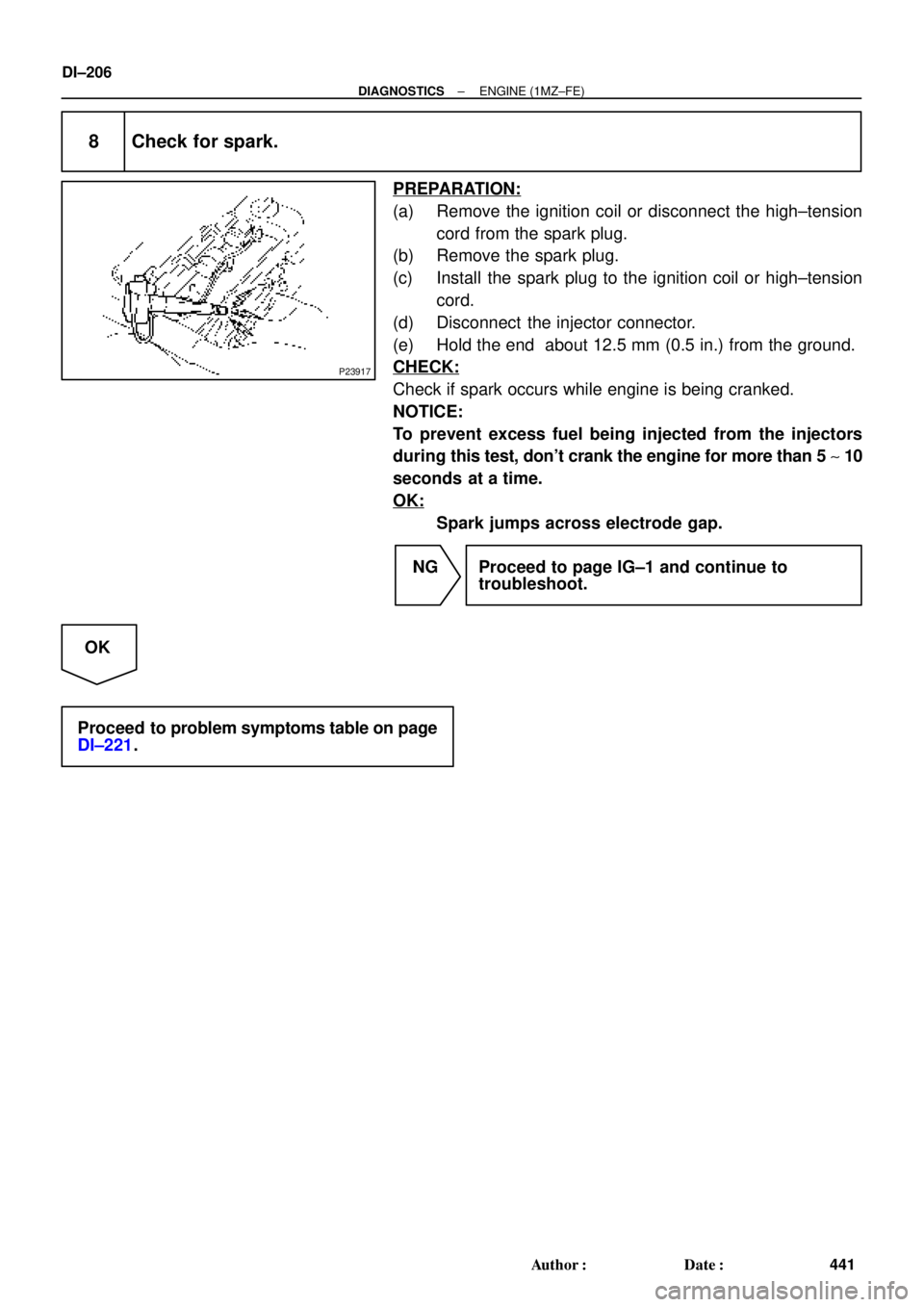
8 Check for spark.
PREPARATION:
(a) Remove the ignition coil or disconnect the high±tension
cord from the spark plug.
(b) Remove the spark plug.
(c) Install the spark plug to the ignition coil or high±tension
cord.
(d) Disconnect the injector connector.
(e) Hold the end about 12.5 mm (0.5 in.) from the ground.
CHECK:
Check if spark occurs while engine is being cranked.
NOTICE:
To prevent excess fuel being injected from the injectors
during this test, don't crank the engine for more than 5 ~ 10
seconds at a time.
OK:
Spark jumps across electrode gap.
NG Proceed to page IG±1 and continue to
troubleshoot.
OK
Proceed to problem symptoms table on page
DI±221.
Page 2631 of 4770

DI±211
446 Author�: Date�:
DIAGNOSTIC TROUBLE CODE CHART
1. SAE CONTROLLED
HINT:
Parameters listed in the chart may not be exactly the same as your reading du")
DI07B±07
± DIAGNOSTICSENGINE (1MZ±FE)
DI±211
446 Author�: Date�:
DIAGNOSTIC TROUBLE CODE CHART
1. SAE CONTROLLED
HINT:
Parameters listed in the chart may not be exactly the same as your reading due to the type of instrument
or other factors.
If a malfunction code is displayed during the DTC check in check mode, check the circuit for that code listed
in the table below. For details of each code, turn to the page referred to under the ''See page '' for the respec-
tive ''DTC No.'' in the DTC chart.
DTC No.
(See Page)Detection ItemTrouble AreaMIL*1Memory
P0100
(DI±222)Mass Air Flow Circuit
Malfunction�Open or short in mass air flow meter circuit
�Mass air flow meter
�ECM
��
P0101
(DI±227)Mass Air Flow Circuit
Range/Performance
Problem
�Mass air flow meter��
P0110
(DI±228)Intake Air Temp. Circuit
Malfunction�Open or short in intake air temp. sensor circuit
�Intake air temp. sensor (built into mass air flow meter)
�ECM
��
P0115
(DI±233)Engine Coolant Temp. Circuit
Malfunction�Open or short in engine coolant temp. sensor circuit
�Engine coolant temp. sensor
�ECM
��
P0116
(DI±237)Engine Coolant Temp. Circuit
Range/Performance Problem�Engine coolant temp. sensor
�Cooling system��
P0120
(DI±239)Throttle/Pedal Position
Sensor/Switch ºAº Circuit
Malfunction�Open or short in throttle position sensor circuit
�Throttle position sensor
�ECM
��
P0121
(DI±243)Throttle/Pedal Position
Sensor/Switch ºAº Circuit
Range/Performance Problem
�Throttle position sensor��
*2
P0125
(DI±244)
Insufficient Coolant Temp. for
Closed Loop Fuel Control
(Except California Spec.)
�Fuel system
�Injector
�Ignition system
�Gas leakage on exhaust system
�Open or short in heated oxygen sensor circuit
(bank 1, 2 sensor 1)
�Heated oxygen sensor (bank 1, 2 sensor 1)
�ECM
��
*3
P0125
(DI±249)
Insufficient Coolant Temp. for
Closed Loop Fuel Control
(Only for California Spec.)
�Fuel system
�Injector
�Ignition system
�Gas leakage on exhaust system
�Open or short in A/F sensor circuit (bank 1, 2 sensor 1)
�A/F sensor (bank 1, 2 sensor 1)
�ECM
��
*2
P0130
(DI±255)Heated Oxygen Sensor Circuit
Malfunction (Bank 1 Sensor 1)�Heated oxygen sensor
�Fuel trim malfunction��
*1: ����� MIL lights up
*
2: Except California specification vehicles
*
3: Only for California specification vehicle
Page 2634 of 4770

449 Author�: Date�:
DTC No.
(See Page)Detection ItemTrouble AreaMIL*Memory
P0440
(DI±311)Evaporative Emission Control
System Malfunction
�Vapor pressure sensor")
DI±214
± DIAGNOSTICSENGINE (1MZ±FE)
449 Author�: Date�:
DTC No.
(See Page)Detection ItemTrouble AreaMIL*Memory
P0440
(DI±311)Evaporative Emission Control
System Malfunction
�Vapor pressure sensor
�Fuel tank cap incorrectly installed
�Fuel tank cap cracked or damaged
�Vacuum hose cracked, holed, blocked, damaged or
disconnected ((1) or (2) in fig. 1)
�Hose or tube cracked, holed, damaged or loose seal
((3) in fig. 1)
�Fuel tank cracked, holed or damaged
�Charcoal canister cracked, holed or damaged
�Fuel tank over fill check valve cracked or damaged
�*1�
P0441
(DI±318)Evaporative Emission Control
System Incorrect Purge Flow
�Open or short in VSV circuit for EVAP
�Open or short in VSV circuit for vapor pressure sensor
�Open or short in vapor pressure sensor circuit
�VSV for EVAP
�VSV for vapor pressure sensor
�Vapor pressure sensor
�Vacuum hose cracks, holed blocked, damaged or
disconnected ((1), (4), (5), (6) and (7) in fig.1)
�Charcoal canister cracks, holed or damaged
�Fuel tank over fill check valve cracked or damaged
��
P0446
(DI±318)Evaporative Emission Control
System Vent Control
Malfunction
�Open or short in VSV circuit for EVAP
�Open or short in VSV circuit for vapor pressure sensor
�Open or short in vapor pressure sensor circuit
�VSV for EVAP
�VSV for vapor pressure sensor
�Vapor pressure sensor
�Vacuum hose cracks, holed blocked, damaged or
disconnected ((1), (4), (5), (6) and (7) in fig.1)
�Charcoal canister cracks, holed or damaged
�Fuel tank over fill check valve cracked or damaged
��
P0450
(DI±331)Evaporative Emission Control
System Pressure Sensor
Malfunction�Open or short in vapor pressure sensor circuit
�Vapor pressure sensor
�ECM
��
P0451
(DI±331)Evaporative Emission Control
System Pressure Sensor
Range/Performance�Open or short in vapor pressure sensor circuit
�Vapor pressure sensor
�ECM
��
P0500
(DI±333)Vehicle Speed Sensor
Malfunction
�Open or short in speed sensor circuit
�Vehicle speed sensor
�Combination meter
�ECM
��
P0505
(DI±336)Idle Control System
Malfunction
�IAC valve is stuck or closed
�Open or short in IAC valve circuit
�Open or short in A/C signal circuit
�Air intake (hose loose)
��
*: ����� MIL lights up
Page 2644 of 4770
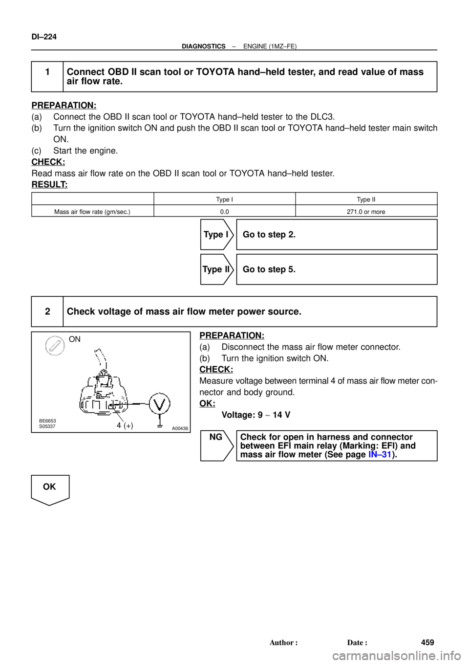
A00436
ON
4 (+)
BE6653
S05337
DI±224
± DIAGNOSTICSENGINE (1MZ±FE)
459 Author�: Date�:
1 Connect OBD II scan tool or TOYOTA hand±held tester, and read value of mass
air flow rate.
PREPARATION:
(a) Connect the OBD II scan tool or TOYOTA hand±held tester to the DLC3.
(b) Turn the ignition switch ON and push the OBD II scan tool or TOYOTA hand±held tester main switch
ON.
(c) Start the engine.
CHECK:
Read mass air flow rate on the OBD II scan tool or TOYOTA hand±held tester.
RESULT:
Type IType II
Mass air flow rate (gm/sec.)0.0271.0 or more
Type I Go to step 2.
Type II Go to step 5.
2 Check voltage of mass air flow meter power source.
PREPARATION:
(a) Disconnect the mass air flow meter connector.
(b) Turn the ignition switch ON.
CHECK:
Measure voltage between terminal 4 of mass air flow meter con-
nector and body ground.
OK:
Voltage: 9 ~ 14 V
NG Check for open in harness and connector
between EFI main relay (Marking: EFI) and
mass air flow meter (See page IN±31).
OK
Page 2645 of 4770
A02017
VG (+)
± DIAGNOSTICSENGINE (1MZ±FE)
DI±225
460 Author�: Date�:
3 Check voltage between terminal VG of ECM connector and body ground.
PREPARATION:
(a) Remove the glove compartment (See page SF±73).
(b) Start the engine.
CHECK:
Measure voltage between terminal VG of the ECM connector
and body ground while engine is idling.
OK:
Voltage:
1.1 ~ 1.5 V (P or N position and A/C switch OFF)
OK Check and replace ECM (See page IN±31).
NG
4 Check for open and short in harness and connector between mass air flow meter
and ECM (See page IN±31).
NG Repair or replace harness or connector.
OK
Replace mass air flow meter.
Page 2646 of 4770
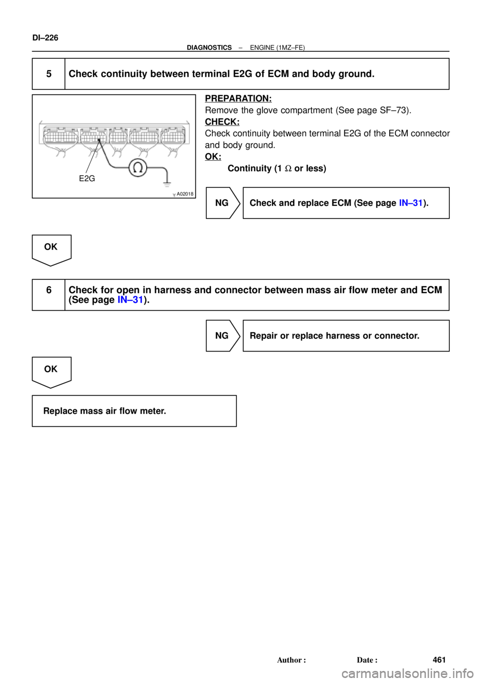
A02018
E2G
DI±226
± DIAGNOSTICSENGINE (1MZ±FE)
461 Author�: Date�:
5 Check continuity between terminal E2G of ECM and body ground.
PREPARATION:
Remove the glove compartment (See page SF±73).
CHECK:
Check continuity between terminal E2G of the ECM connector
and body ground.
OK:
Continuity (1 W or less)
NG Check and replace ECM (See page IN±31).
OK
6 Check for open in harness and connector between mass air flow meter and ECM
(See page IN±31).
NG Repair or replace harness or connector.
OK
Replace mass air flow meter.