Page 2661 of 4770
A00437
1 (+) ON
BE6653
S05338
S05339
1
2
3
± DIAGNOSTICSENGINE (1MZ±FE)
DI±241
476 Author�: Date�:
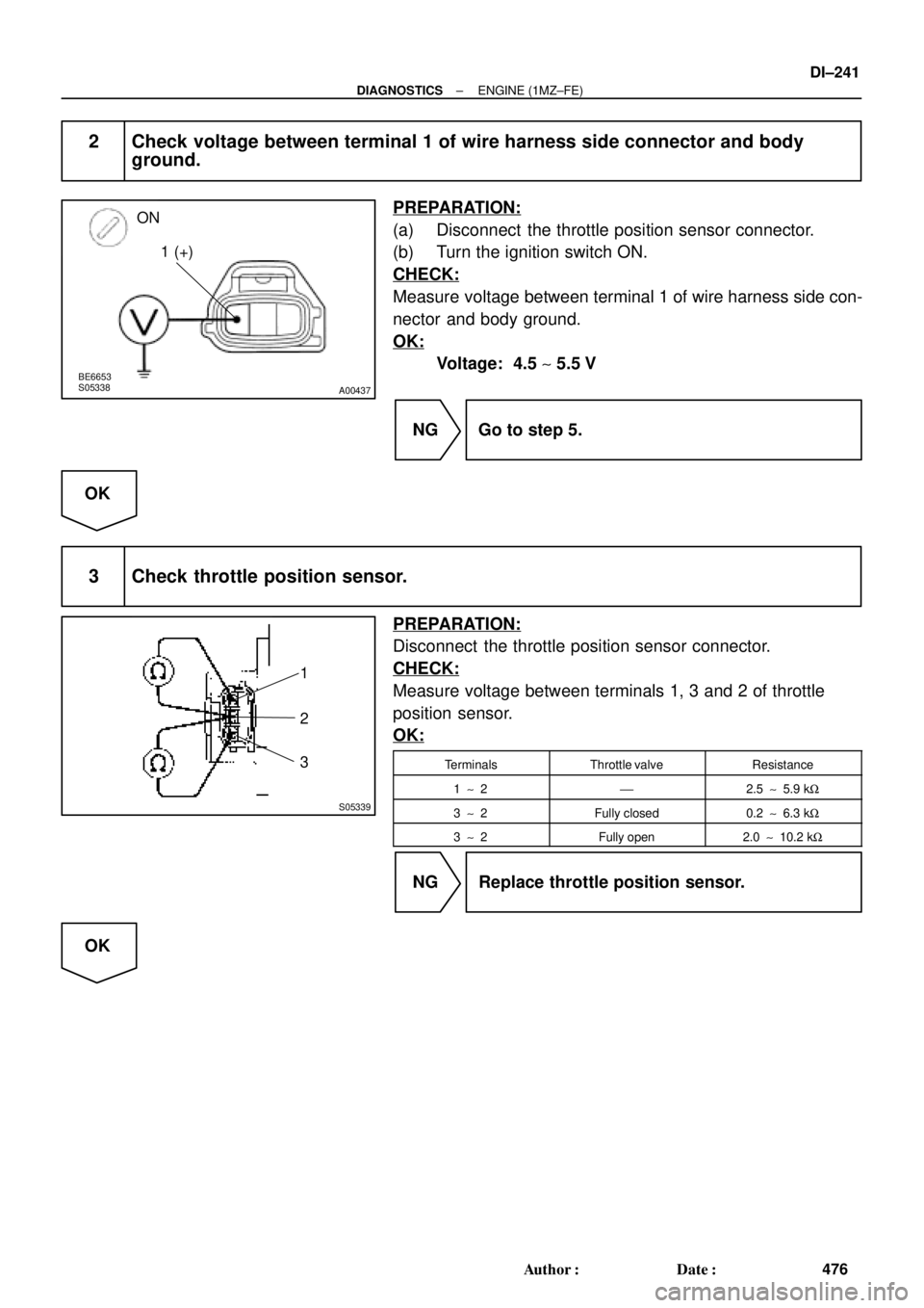
2 Check voltage between terminal 1 of wire harness side connector and body
ground.
PREPARATION:
(a) Disconnect the throttle position sensor connector.
(b) Turn the ignition switch ON.
CHECK:
Measure voltage between terminal 1 of wire harness side con-
nector and body ground.
OK:
Voltage: 4.5 ~ 5.5 V
NG Go to step 5.
OK
3 Check throttle position sensor.
PREPARATION:
Disconnect the throttle position sensor connector.
CHECK:
Measure voltage between terminals 1, 3 and 2 of throttle
position sensor.
OK:
TerminalsThrottle valveResistance
1 ~ 2'2.5 ~ 5.9 kW
3 ~ 2Fully closed0.2 ~ 6.3 kW
3 ~ 2Fully open2.0 ~ 10.2 kW
NG Replace throttle position sensor.
OK
Page 2662 of 4770
A02021
ON
VTA1 (+) E2 (±)
A02022
ON
VC (+) E2 (±)
DI±242
± DIAGNOSTICSENGINE (1MZ±FE)
477 Author�: Date�:
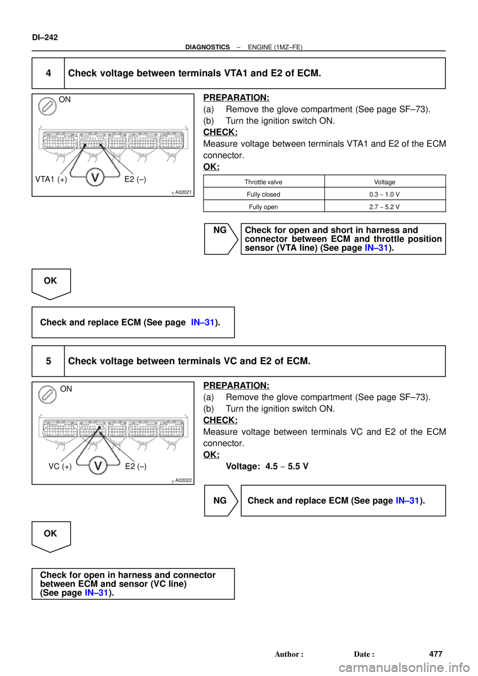
4 Check voltage between terminals VTA1 and E2 of ECM.
PREPARATION:
(a) Remove the glove compartment (See page SF±73).
(b) Turn the ignition switch ON.
CHECK:
Measure voltage between terminals VTA1 and E2 of the ECM
connector.
OK:
Throttle valveVoltage
Fully closed0.3 ~ 1.0 V
Fully open2.7 ~ 5.2 V
NG Check for open and short in harness and
connector between ECM and throttle position
sensor (VTA line) (See page IN±31).
OK
Check and replace ECM (See page IN±31).
5 Check voltage between terminals VC and E2 of ECM.
PREPARATION:
(a) Remove the glove compartment (See page SF±73).
(b) Turn the ignition switch ON.
CHECK:
Measure voltage between terminals VC and E2 of the ECM
connector.
OK:
Voltage: 4.5 ~ 5.5 V
NG Check and replace ECM (See page IN±31).
OK
Check for open in harness and connector
between ECM and sensor (VC line)
(See page IN±31).
Page 2666 of 4770
DI±246
± DIAGNOSTICSENGINE (1MZ±FE)
481 Author�: Date�:
1 Are there any other codes (besides DTC P0125) being output ?
YES Go to relevant DTC chart.
NO
2 Connect OBD II scan tool or TOYOTA hand±held tester, and read value for
voltage output of heated oxygen sensors (bank 1, 2 sensor 1).
PREPARATION:
(a) Connect the OBD II scan tool or TOYOTA hand±held tester to the DLC3.
(b) Warm up the engine to normal operating temp.(above 75°C (169°F)).
CHECK:
Read voltage output of the heated oxygen sensors (bank 1,2 sensor 1) when engine is suddenly raced.
HINT:
Perform quick racing to 4,000 rpm 3 times using accelerator pedal.
OK:
Heated oxygen sensors (bank 1, 2 sensor 1) output a RICH signal
(0.45 V or more) at least once.
OK Go to step 10.
NG
3 Check for open and short in harness and connector between ECM and heated
oxygen sensors (bank 1, 2 sensor 1) (See page IN±31).
NG Repair or replace harness or connector.
OK
Page 2667 of 4770
± DIAGNOSTICSENGINE (1MZ±FE)
DI±247
482 Author�: Date�:
4 Check whether misfire is occurred or not by monitoring DTC and data list.
NG Perform troubleshooting for misfire
(See page DI±351).
OK
5 Check air induction system (See page SF±1).
NG Repair or replace.
OK
6 Check EGR system (See page EC±11).
NG Replace EGR system.
OK
7 Check fuel pressure (See page SF±6).
NG Check and repair fuel pump, fuel pipe line and
filter (See page SF±1).
OK
8 Check injector injection (See page SF±25)
NG Replace injector.
OK
Page 2668 of 4770
DI±248
± DIAGNOSTICSENGINE (1MZ±FE)
483 Author�: Date�:
9 Check gas leakage on exhaust system.
NG Repair or replace.
OK
Replace heated oxygen sensors
(bank 1, 2 sensor 1).
10 Perform confirmation driving pattern (See page DI±255).
Go
11 Is there DTC P0125 being output again ?
YES Check and replace ECM
(See page IN±31).
NO
12 Did vehicle runs out of fuel in the past ?
NO Check for intermittent problems
(See page DI±197).
NO
DTC P0125 is caused by running out of fuel.
Page 2672 of 4770

487 Author�: Date�:
2 Connect the OBD II scan tool or TOYOTA hand±held tester, and read value for
voltage output of A/F sensors (bank 1, 2 sensor 1).
PREPARATIO")
DI±252
± DIAGNOSTICSENGINE (1MZ±FE)
487 Author�: Date�:
2 Connect the OBD II scan tool or TOYOTA hand±held tester, and read value for
voltage output of A/F sensors (bank 1, 2 sensor 1).
PREPARATION:
(a) Connect the OBD II scan tool or TOYOTA hand±held tester to the DLC3.
(b) Warm up the A/F sensors (bank 1, 2 sensor 1) with the engine at 2,500 rpm for approx. 90 sec.
CHECK:
Read voltage value of A/F sensors (bank 1, 2 sensor 1) on the screen of OBD II scan tool or TOYOTA hand±
held tester, when you perform all the following conditions.
HINT:
The voltage of AFR�,AFL� terminal of ECM is 3.3 fixed and the AFR�,AFL� terminal is 3.0 V fixed.
Therefore, it is impossible to check the A/F sensor output voltage at the terminals (AFR�,AFL�/
AFR�,AFL�) of ECM.
OK:
ConditionA/F Sensor Voltage value
Engine idlingN t i t 3 3 V (*0 660 V)E i idli�Not remains at 3.3. V (*0.660 V)Engine idlingNot remains at 3.3. V ( 0.660 V)
�Not remains at38V(
*0 76 V) or more
Driving at engine speed 1,500 rpm or more and vehicle
speed 40 km/h (25 mph) or move, and operate throttle valve
open and close
�Not remains at 3.8 V (*0.76 V) or more
�Not remains at 2.8 V (*0.56 V) or less
*: When you use the OBD II scan tool (excluding TOYOTA hand±held tester)
HINT:
�During fuel enrichment, there is a case that the output voltage of A/F sensors (bank 1, 2 sensor 1) is
below 2.8 V (
* 0.56 V), it is normal.
�During fuel cut, there is a case that the output voltage of A/F sensors (bank 1, 2 sensor 1) is above
3.8 V (
* 0.76 V), it is normal.
�
If output voltage of A/F sensors (bank 1, 2 sensor 1) remains at 3.30 V (* 0.660 V) even after performing
all the above conditions, A/F sensors (bank 1, 2 sensor 1) circuit may be open.
�If output voltage of A/F sensor remains at 3.8 V (* 0.76 V) or more, or 2.8 V (* 0.56 V) or less even after
performing all the above conditions, A/F sensors (bank 1, 2 sensor 1) circuit may be short.
*: When you use the OBD II scan tool (excluding TOYOTA hand±held tester).
OK Go to step 10.
NG
3 Check for open and short in harness and connector between ECM and A/F
sensors (bank1, 2 sensor1) (See page IN±31).
NG Repair or replace harness or connector.
OK
Page 2673 of 4770
± DIAGNOSTICSENGINE (1MZ±FE)
DI±253
488 Author�: Date�:
4 Check resistance of A/F sensor heaters (bank1, 2 sensor1) (See page SF±68).
NG Replace A/F sensor.
OK
5 Check air induction system (See page SF±1).
NG Repair or replace.
OK
6 Check EGR system (See page EC±11).
NG Replace EGR system.
OK
7 Check fuel pressure (See page SF±21).
NG Check and repair fuel pump, fuel pipe line and
filter (See page SF±1).
OK
8 Check injector injection (See page SF±25).
NG Replace injector.
OK
Page 2674 of 4770
DI±254
± DIAGNOSTICSENGINE (1MZ±FE)
489 Author�: Date�:
9 Check gas leakage on exhaust system.
NG Repair or replace
OK
Replace A/F sensors (bank1, 2 sensor1).
10 Perform confirmation driving pattern (See page DI±340).
Go
11 Is there DTC P0125 being output again ?
YES Check and replace ECM
(See page IN±31).
NO
12 Did vehicle runs out of fuel in the past ?
NO Check for intermittent problems
(See page DI±197).
YES
DTC P0125 is caused by running out of fuel.