Page 2675 of 4770

(5)Idling
IG SW OFF
1 ~ 3 min. 1 min.Time
(2)
(1)(3)(4)
± DIAGNOSTICSENGINE (1MZ±FE)
DI±255
490 Author�: Date�:
DTC P0130 Heated Oxygen Sensor Circui")
A01666
Vehicle speed
50 ~ 65 km/h
(31 ~ 40 mph)
(5)Idling
IG SW OFF
1 ~ 3 min. 1 min.Time
(2)
(1)(3)(4)
± DIAGNOSTICSENGINE (1MZ±FE)
DI±255
490 Author�: Date�:
DTC P0130 Heated Oxygen Sensor Circuit Malfunction
(Bank 1 Sensor 1) (Except California Spec.)
DTC P0150 Heated Oxygen Sensor Circuit Malfunction
(Bank 2 Sensor 1) (Except California Spec.)
CIRCUIT DESCRIPTION
Refer to DTC P0125 (Insufficient Coolant Temp. for Closed Loop Fuel Control) on page DI±244.
DTC No.DTC Detecting ConditionTrouble Area
P0130
P0150Voltage output of heated oxygen sensor remains at 0.4 V or
more, or 0.55 V or less, during idling after engine is warmed up
(2 trip detection logic)�Heated oxygen sensor
�Fuel trim malfunction
HINT:
Bank 1 refers to the bank that includes cylinder No.1. Bank 2 refers to the bank that does not include cylinder
No.1. Sensor 1 refers to the sensor closer to the engine body.
The heated oxygen sensor's output voltage and the short-term fuel trim value can be read using the
OBD II scan tool or TOYOTA hand-held tester.
WIRING DIAGRAM
Refer to DTC P0125 (Insufficient Coolant Temp. for Closed Loop Fuel Control) on page DI±244.
CONFIRMATION DRIVING PATTERN
(1) Connect the TOYOTA hand±held tester to the DLC3.
(2) Switch the TOYOTA hand±held tester from normal mode to check mode (See page DI±197).
(3) Start the engine and warm it up with all accessory switches OFF.
(4) Drive the vehicle at 50 ~ 65 km/h (31 ~ 40 mph) for 1 ~ 3 min. to warm up the heated oxygen sensor.
(5) Let the engine idle for 1 min.
(6) Perform steps (3) to (5) three times.
DI07N±07
Page 2676 of 4770

491 Author�: Date�:
HINT:
If a malfunction exists, the MIL will light up during step (6).
NOTICE:
If the conditions in this test are not strictly followed")
P18349
DI±256
± DIAGNOSTICSENGINE (1MZ±FE)
491 Author�: Date�:
HINT:
If a malfunction exists, the MIL will light up during step (6).
NOTICE:
If the conditions in this test are not strictly followed, detection of the malfunction will not be possible.
If you do not have a TOYOTA hand±held tester, turn the ignition switch OFF after performing steps
(3) to (6), then perform steps (3) to (6) again.
INSPECTION PROCEDURE
HINT:
Read freeze frame data using TOYOTA hand±held tester or OBD II scan tool. Because freeze frame records
the engine conditions when the malfunction is detected, when troubleshooting it is useful for determining
whether the vehicle was running or stopped, the engine warmed up or not, the air±fuel ratio lean or rich, etc.
at the time of the malfunction.
1 Are there any other codes (besides DTC P0130, P0150) being output ?
YES Go to relevant DTC chart.
NO
2 Check the output voltage of heated oxygen sensors (bank1, 2 sensor1)
during idling.
PREPARATION:
Warm up the heated oxygen sensors (bank1, 2 sensor1) with the engine at 2,500 rpm for approx. 90 sec.
CHECK:
Use the OBD II scan tool or TOYOTA hand±held tester to read the output voltage of the heated oxygen sen-
sors (bank1, 2 sensor1) during idling.
OK:
Heated oxygen sensors (bank1, 2 sensor1) output voltage:
Alternates repeatedly between less than 0.4 V and more than 0.55 V (See the following table).
OK Go to step 8.
NG
Page 2677 of 4770
± DIAGNOSTICSENGINE (1MZ±FE)
DI±257
492 Author�: Date�:
3 Check for open and short in harness and connector between ECM and heated
oxygen sensors (bank1, 2 sensor1) (See page IN±31).
NG Repair or replace harness or connector.
OK
4 Check air induction system (See page SF±1).
NG Repair or replace.
OK
5 Check EGR system (See page EC±11).
NG Replace EGR system.
OK
6 Check fuel pressure (See page SF±6).
NG Check and repair fuel pump, fuel pipe line and
filter (See page SF±1).
OK
Page 2678 of 4770
DI±258
± DIAGNOSTICSENGINE (1MZ±FE)
493 Author�: Date�:
7 Check injector injection (See page SF±25).
NG Replace injector.
OK
Replace heated oxygen sensors
(bank1, 2 sensor1).
8 Perform confirmation driving pattern.
Go
9 Are there DTC P0130 and/or P0150 being output again ?
NO Check for intermittent problems
(see page DI±197).
YES
Check and replace ECM
(See page IN±31).
Page 2680 of 4770
P18349
DI±260
± DIAGNOSTICSENGINE (1MZ±FE)
495 Author�: Date�:
2 Check the output voltage of heated oxygen sensors (bank1, 2 sensor1)
during idling.
PREPARATION:
Warm up the heated oxygen sensors (bank1, 2 sensor1) with the engine at 2,500 rpm for approx. 90 sec.
CHECK:
Use the OBD II scan tool or TOYOTA hand±held tester to read the output voltage of the heated oxygen sen-
sors (bank1, 2 sensor1) during idling.
OK:
Heated oxygen sensors (bank1, 2 sensor1) output voltage:
Alternates repeatedly between less than 0.4 V and more than 0.55 V (See the following table).
OK Go to step 8.
NG
3 Check for open and short in harness and connector between ECM and heated
oxygen sensors (bank1, 2 sensor1) (See page IN±31).
NG Repair or replace harness or connector.
OK
4 Check air induction system (See page SF±1).
NG Repair or replace.
OK
Page 2681 of 4770
± DIAGNOSTICSENGINE (1MZ±FE)
DI±261
496 Author�: Date�:
5 Check EGR system (See page EC±11).
NG Replace EGR system.
OK
6 Check fuel pressure (See page SF±1).
NG Check and repair fuel pump, fuel pipe line and
filter (See page SF±1).
OK
7 Check injector injection (See page SF±25).
NG Replace injector.
OK
Replace heated oxygen sensors
(bank1, 2 sensor1).
8 Perform confirmation driving pattern (See page DI±255).
Go
Page 2682 of 4770
DI±262
± DIAGNOSTICSENGINE (1MZ±FE)
497 Author�: Date�:
9 Are there DTC P0133 and/or P0153 being output again ?
NO Check for intermittent problems
(see page DI±197).
YES
Check and Replace ECM
(See page IN±31).
Page 2684 of 4770
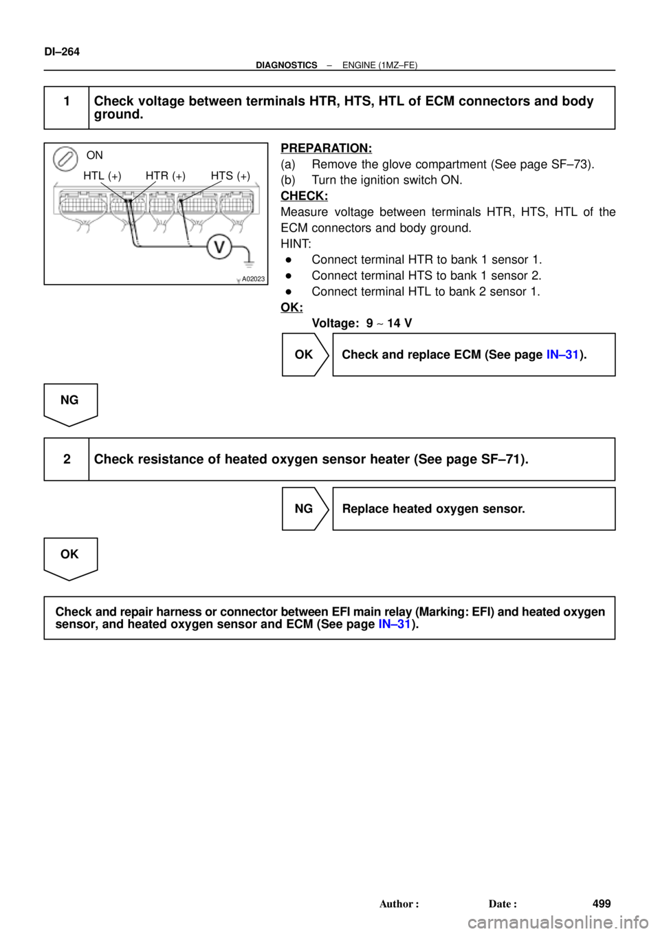
A02023
ON
HTL (+) HTR (+) HTS (+)
DI±264
± DIAGNOSTICSENGINE (1MZ±FE)
499 Author�: Date�:
1 Check voltage between terminals HTR, HTS, HTL of ECM connectors and body
ground.
PREPARATION:
(a) Remove the glove compartment (See page SF±73).
(b) Turn the ignition switch ON.
CHECK:
Measure voltage between terminals HTR, HTS, HTL of the
ECM connectors and body ground.
HINT:
�Connect terminal HTR to bank 1 sensor 1.
�Connect terminal HTS to bank 1 sensor 2.
�Connect terminal HTL to bank 2 sensor 1.
OK:
Voltage: 9 ~ 14 V
OK Check and replace ECM (See page IN±31).
NG
2 Check resistance of heated oxygen sensor heater (See page SF±71).
NG Replace heated oxygen sensor.
OK
Check and repair harness or connector between EFI main relay (Marking: EFI) and heated oxygen
sensor, and heated oxygen sensor and ECM (See page IN±31).