Page 2705 of 4770
FI6510FI6607A00113
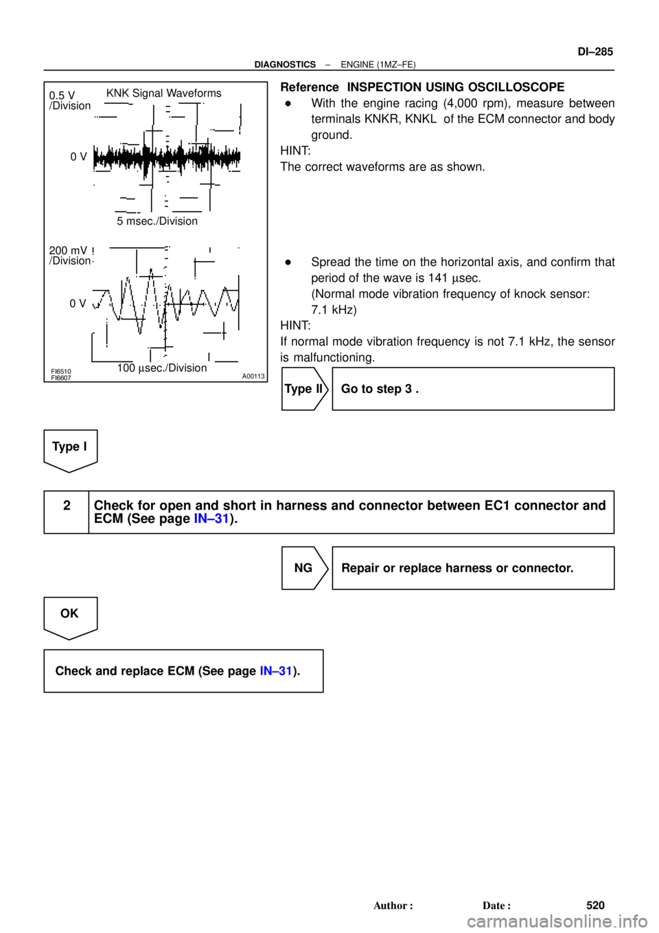
KNK Signal Waveforms
0.5 V
/Division
5 msec./Division
100 msec./Division 0 V
200 mV
/Division
0 V
± DIAGNOSTICSENGINE (1MZ±FE)
DI±285
520 Author�: Date�:
Reference INSPECTION USING OSCILLOSCOPE
�With the engine racing (4,000 rpm), measure between
terminals KNKR, KNKL of the ECM connector and body
ground.
HINT:
The correct waveforms are as shown.
�Spread the time on the horizontal axis, and confirm that
period of the wave is 141 msec.
(Normal mode vibration frequency of knock sensor:
7.1 kHz)
HINT:
If normal mode vibration frequency is not 7.1 kHz, the sensor
is malfunctioning.
Type II Go to step 3 .
Type I
2 Check for open and short in harness and connector between EC1 connector and
ECM (See page IN±31).
NG Repair or replace harness or connector.
OK
Check and replace ECM (See page IN±31).
Page 2706 of 4770
DI±286
± DIAGNOSTICSENGINE (1MZ±FE)
521 Author�: Date�:
3 Check for open and short in harness and connector between EC1 connector and
knock sensor (See page IN±31).
HINT:
�If DTC P0325 has changed to P0330, check the knock sensor circuit on the right bank side.
�If DTC P0330 has changed to P0325, check the knock sensor circuit on the left bank side.
NG Repair or replace harness or connector.
OK
Replace knock sensor.
Page 2708 of 4770
FI7059
FI7060
A00069
G22, NE Signal Waveforms
G22
G22NE
NE5 V
/Division
5 V
/Division 20 msec./Division (Idling)
10 msec./Division (Idling)
DI±288
± DIAGNOSTICSENGINE (1MZ±FE)
523 Author�: Date�:
1 Check resistance of crankshaft position sensor (See page IG±12).
Reference INSPECTION USING OSCILLOSCOPE
During cranking or idling, check between terminals G22+ and
NE±, NE and NE± of the ECM connector.
HINT:
The correct waveforms are as shown.
NG Replace crankshaft position sensor.
OK
2 Check for open and short in harness and connector between ECM and
crankshaft position sensor (See page IN±31).
NG Repair or replace harness or connector.
OK
Page 2709 of 4770
± DIAGNOSTICSENGINE (1MZ±FE)
DI±289
524 Author�: Date�:
3 Inspect sensor installation and teeth of crankshaft timing pulley.
NG Tighten the sensor.
Replace crankshaft timing pulley.
OK
Check and replace ECM
(See page IN±31).
Page 2710 of 4770

525 Author�: Date�:
DTC P0340 Camshaft Position Sensor Circuit
Malfunction
CIRCUIT DESCRIPTION
Camshaft position sensor (G22 signal) consist of a signal plate an")
DI±290
± DIAGNOSTICSENGINE (1MZ±FE)
525 Author�: Date�:
DTC P0340 Camshaft Position Sensor Circuit
Malfunction
CIRCUIT DESCRIPTION
Camshaft position sensor (G22 signal) consist of a signal plate and pickup coil.
The G22 signal plate has one tooth, on its outer circumference and is mounted on the left bank camshafts.
When the camshafts rotate, the protrusion on the signal plate and the air gap on the pickup coil change,
causing fluctuations in the magnetic field and generating an electromotive force in the pickup coil.
The NE signal plate has 34 teeth and is mounted on the crankshaft. The NE signal sensor generates 34
signals for every engine revolution. The ECM detects the standard crankshaft angle based on the G22 signal
and the actual crankshaft angle and the engine speed by the NE signals.
DTC No.DTC Detecting ConditionTrouble Area
P0340
No camshaft position sensor signal to ECM during cranking
(2 trip detection logic)�Open or short in camshaft position sensor circuit
�Camshaft position sensor
P0340No camshaft position sensor signal to ECM with engine speed
600 rpm or more
�Camshaft osition sensor
�Starter
�ECM
WIRING DIAGRAM
Refer to DTC P0335 (Crankshaft Position Sensor ºAº Circuit Malfunction) on page DI±287 .
INSPECTION PROCEDURE
HINT:
Read freeze frame data using TOYOTA hand±held tester or OBD II scan tool. Because freeze frame records
the engine conditions when the malfunction is detected, when troubleshooting it is useful for determining
whether the vehicle was running or stopped, the engine warmed up or not, the air±fuel ratio lean or rich, etc.
at the time of the malfunction.
1 Check resistance of camshaft position sensor (See page IG±1).
Reference INSPECTION USING OSCILLOSCOPE
Refer to DTC P0335 on page DI±287.
NG Replace camshaft position sensor.
OK
DI07V±06
Page 2711 of 4770
± DIAGNOSTICSENGINE (1MZ±FE)
DI±291
526 Author�: Date�:
2 Check for open and short in harness and connector between ECM and camshaft
position sensor (See page IN±31).
NG Repair or replace harness or connector.
OK
3 Inspect sensor installation and tooth of left bank camshaft timing pulley.
NG Tighten the sensor.
Replace left bank camshaft timing pulley.
OK
Check and replace ECM (See page IN±31).
Page 2713 of 4770
A07446
J20
Junction
Connector
EFI Relay
2K2J
2C
BB±YJ27 J28
W±B
EB
9B±Y Y±G
AA1218
13 1
2
G±Y
BRECM
EGR
E01
EGLS5 V
E2 32
VC
5 V
THG
E7
2
1W±GY
BR18
8
MREL
B+ BR
EGR Gas Temp. Sensor
E10 E10
22
E11 E10E11
Engine Room J/B
2A2
7 1
53
1 5
EFI
VSV
for EGR
B±Y
Junction
Connector
B
2
B±Y
J35
J35C
C Junction
ConnectorB±W
B±W
B±W
EGR Valve
Position Sensor
II3From
FL MAIN
S06906
Vehicle Speed
70 ~ 90 km/h
(43 ~ 56 mph)
Idling
IG SW OFF(1)(2)(3)
(4)(5)
Warmed up 3 ~ 5 min. 3 min. 3 ~ 5 min. 2 min.Time
± DIAGNOSTICSENGINE (1MZ±FE)
DI±293
528 Author�: Date�:
WIRING DIAGRAM
SYSTEM CHECK DRIVING PATTERN
Page 2714 of 4770

529 Author�: Date�:
(1) Connect the OBD II scan tool or TOYOTA hand±held tester to the DLC3.
(2) Start and warm up the engine with all accessories switched OFF.")
DI±294
± DIAGNOSTICSENGINE (1MZ±FE)
529 Author�: Date�:
(1) Connect the OBD II scan tool or TOYOTA hand±held tester to the DLC3.
(2) Start and warm up the engine with all accessories switched OFF.
(3) Run the vehicle at 70 ~ 90 km/h (43 ~ 56 mph) for 3 min. or more.
(4) Idle the engine for about 2 min.
(5) Do steps (3) and (4) again.
(6) Stop at safe place and turn the ignition switch OFF.
(7) Do step (2) to (5) again.
(8) Check the READINESS TESTS mode on the OBD II scan tool or TOYOTA hand±held tester.
If COMPL is displayed and the MIL does not light up, the system is normal.
If INCMPL is displayed and the MIL does not light up, run the vehicle steps (2) to (6) from some times and
check it.
HINT:
INCMPL is displayed when either condition (a) or (b) exists.
(a) The system check is incomplete.
(b) There is a malfunction in the system.
If there is a malfunction in the system, the MIL light up after step (7) above is done.
(2trip detection logic)
INSPECTION PROCEDURE
HINT:
Read freeze frame data using TOYOTA hand±held tester or OBD II scan tool. Because freeze frame records
the engine conditions when the malfunction is detected, when troubleshooting it is useful for determining
whether the vehicle was running or stopped, the engine warmed up or not, the air±fuel ratio lean or rich, etc.
at the time of the malfunction.
TOYOTA hand±held tester
1 Connect TOYOTA hand±held tester, and read value of EGR gas temperature.
PREPARATION:
(a) Connect the TOYOTA hand±held tester to the DLC3.
(b) Warm up the engine.
CHECK:
Read EGR gas temperature on TOYOTA hand±held tester during idling.
OK:
EGR gas temperature : 55C (415F) ~ 1505C (3025F) (Not immediately after driving)
HINT:
If there is an open circuit, TOYOTA hand±held tester indicates 3.15C (37.65F).
If there is an short circuit, TOYOTA hand±held tester indicates 159.35C (318.75F).
OK Go to step 4.
NG