Page 2723 of 4770
± DIAGNOSTICSENGINE (1MZ±FE)
DI±303
538 Author�: Date�:
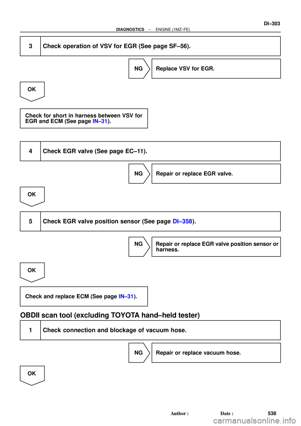
3 Check operation of VSV for EGR (See page SF±56).
NG Replace VSV for EGR.
OK
Check for short in harness between VSV for
EGR and ECM (See page IN±31).
4 Check EGR valve (See page EC±11).
NG Repair or replace EGR valve.
OK
5 Check EGR valve position sensor (See page DI±358).
NG Repair or replace EGR valve position sensor or
harness.
OK
Check and replace ECM (See page IN±31).
OBDII scan tool (excluding TOYOTA hand±held tester)
1 Check connection and blockage of vacuum hose.
NG Repair or replace vacuum hose.
OK
Page 2724 of 4770
DI±304
± DIAGNOSTICSENGINE (1MZ±FE)
539 Author�: Date�:
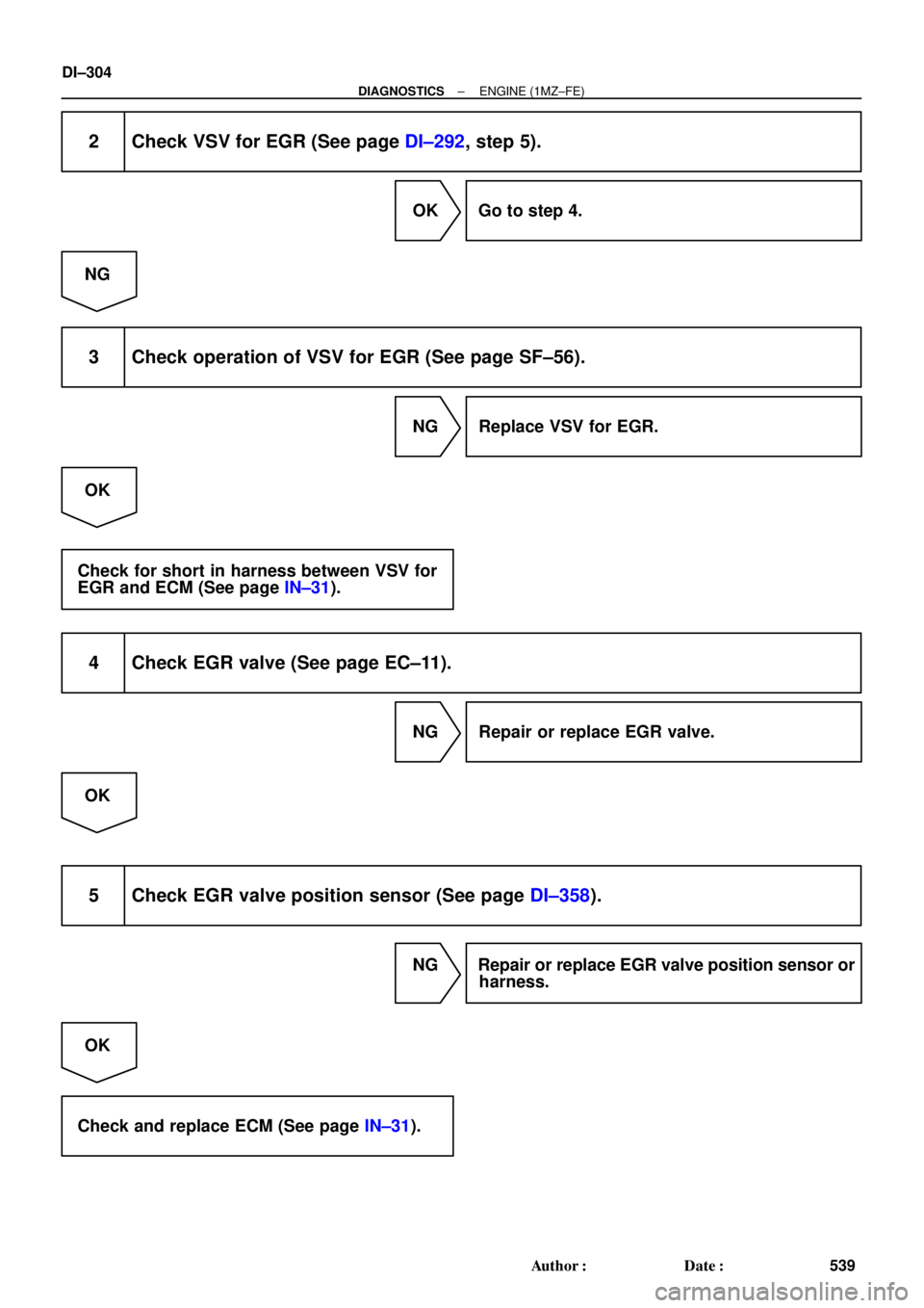
2 Check VSV for EGR (See page DI±292, step 5).
OK Go to step 4.
NG
3 Check operation of VSV for EGR (See page SF±56).
NG Replace VSV for EGR.
OK
Check for short in harness between VSV for
EGR and ECM (See page IN±31).
4 Check EGR valve (See page EC±11).
NG Repair or replace EGR valve.
OK
5 Check EGR valve position sensor (See page DI±358).
NG Repair or replace EGR valve position sensor or
harness.
OK
Check and replace ECM (See page IN±31).
Page 2725 of 4770
(b)(c) (d)
Time Warmed up 3 min. or so")
FI7081
Waveform of Oxygen Sensor
before CatalystNormal Catalyst Waveform of Oxygen Sensor
after Catalyst
FI7132
Engine Speed
2,500 ~ 3,000 rpm
Idling
IG SW OFF(a)(b)(c) (d)
Time Warmed up 3 min. or so Check
± DIAGNOSTICSENGINE (1MZ±FE)
DI±305
540 Author�: Date�:
DTC P0420 Catalyst System Efficiency Below Threshold
(Except California Spec.)
CIRCUIT DESCRIPTION
The ECM compares the waveform of the oxygen sensor located before the catalyst with the waveform of
the oxygen sensor located after the catalyst to determine whether or not catalyst performance has deterio-
rated.
Air±fuel ratio feedback compensation keeps the waveform of the oxygen sensor before the catalyst repeat-
edly changing back and forth from rich to lean.
If the catalyst is functioning normally, the waveform of the oxygen sensor after the catalyst switches back
and forth between rich and lean much more slowly than the waveform of the oxygen sensor before the cata-
lyst.
But when both waveforms change at a similar rate, it indicates that catalyst performance has deteriorated.
DTC No.DTC Detecting ConditionTrouble Area
P0420
After engine and catalyst are warmed up, and while vehicle is
driven within set vehicle and engine speed range, waveforms
of heated oxygen sensors (bank 1 sensor 1, 2) have the same
amplitude
(2 trip detection logic)
�Three±way catalytic converter
�Open or short in heated oxygen sensor circuit
�Heated oxygen sensor
CONFIRMATION ENGINE RACING PATTERN
DI07Y±06
Page 2726 of 4770

1 V
0 V
200 m sec./Division
DI±306
± DIAGNOSTICSENGINE (1MZ±FE)
541 Author�: Date�:
(a) Connect the TOYOTA hand±held tester to the DLC3, or connect the pr")
FI6514
OX Signal Waveform (Oscilloscope)
1 V
0 V
200 m sec./Division
DI±306
± DIAGNOSTICSENGINE (1MZ±FE)
541 Author�: Date�:
(a) Connect the TOYOTA hand±held tester to the DLC3, or connect the probe of the oscilloscope between
terminals OXR1, OXL1, OXS and E1 of the ECM connector.
(b) Start engine and warm it up with all accessories switched OFF until water temp. is stable.
(c) Race the engine at 2,500 ~ 3,000 rpm for about 3 min.
(d) After confirming that the waveform of the heated oxygen sensor, bank 1, 2 sensor 1 (OXR1, OXL1),
oscillate around 0.5 V during feedback to the ECM, check the waveform of the heated oxygen sensor,
bank 1 sensor 2 (OXS).
HINT:
If there is a malfunction in the system, the waveform of the
heated oxygen sensor, bank 1 sensor 2 (OXS), is almost the
same as that of the heated oxygen sensor, bank 1, 2 sensor 1
(OXR1, OXL1), on the left.
There are some cases where, even though a malfunction
exists, the MIL may either light up or not light up.
INSPECTION PROCEDURE
HINT:
Read freeze frame data using TOYOTA hand±held theater or OBD II scan tool. Because freeze frame re-
cords the engine conditions when the malfunction is detected, when troubleshooting it is useful for determin-
ing whether the vehicle was running or stopped, the engine warmed up or not, the air±fuel ratio lean or rich,
etc. at the time of the malfunction.
1 Are there any other codes (besides DTC P0420) being output?
YES Go to relevant DTC chart.
NO
2 Check gas leakage on exhaust system.
NG Repair or replace.
OK
Page 2727 of 4770
± DIAGNOSTICSENGINE (1MZ±FE)
DI±307
542 Author�: Date�:
3 Check heated oxygen sensor (bank 1, sensor 1) (See page DI±255).
NG Repair or replace.
OK
4 Check heated oxygen sensors (bank 1, 2 sensor 2) (See page DI±265).
NG Repair or replace.
OK
Replace three±way catalytic converter.
Page 2729 of 4770

Warmed up3 min. or so
2 sec. 2 sec.
CheckTime (b)(c)
(d)
± DIAGNOSTICSENGINE (1MZ±FE)
DI±309
544 Author�: Date�:
CONFIRMATION ENGINE RACI")
A00479
Engine Speed
3,000 rpm
2,000 rpm
Idling
IG SW OFF(a)
Warmed up3 min. or so
2 sec. 2 sec.
CheckTime (b)(c)
(d)
± DIAGNOSTICSENGINE (1MZ±FE)
DI±309
544 Author�: Date�:
CONFIRMATION ENGINE RACING PATTERN
(a) Connect the OBD II scan tool or TOYOTA hand±held tester to the DLC3.
(b) Start engine and warm it up with all accessories switched OFF until water temp. is stable.
(c) Race the engine at 2,500 ~ 3,000 rpm for about 3 min.
(d) When racing the engine at 3,000 rpm for 2 sec. and 2,000 rpm for 2 sec. alternately, check the wave-
form of the heated oxygen sensor (bank 1 sensor 2).
INSPECTION PROCEDURE
HINT:
Read freeze frame data using TOYOTA hand±held tester or OBD II scan tool. Because freeze frame records
the engine conditions when the malfunction is detected, when troubleshooting it is useful for determining
whether the vehicle was running or stopped, the engine warmed up or not, the air±fuel ratio lean or rich, etc.
at the time of the malfunction.
1 Are there any other codes (besides DTC P0420) being output ?
YES Go to relevant DTC chart.
NO
2 Check gas leakage on exhaust system.
NG Repair or replace.
OK
Page 2730 of 4770
DI±310
± DIAGNOSTICSENGINE (1MZ±FE)
545 Author�: Date�:
3 Check A/F sensors (bank 1, 2 sensor 1) (See page DI±255).
NG Repair or replace.
OK
4 Check heated oxygen sensor (bank 1 sensor 2) (See page DI±265).
NG Repair or replace.
OK
Replace three±way catalytic converter.
Page 2731 of 4770

(2)
(3) fig. 1
(6)
(4)
(5) (7)
Fuel Tank Over Fill
Check Valve
(8)
(9)
± DIAGNOSTICSENGINE")
A01652
ECM
Vapor Pressure
Sensor
VSV for Vapor
Pressure Sensor VSV
for EVAP
Charcoal Canister
Fuel Tank (1)
(2)
(3) fig. 1
(6)
(4)
(5) (7)
Fuel Tank Over Fill
Check Valve
(8)
(9)
± DIAGNOSTICSENGINE (1MZ±FE)
DI±311
546 Author�: Date�:
DTC P0440 Evaporative Emission Control System
Malfunction
CIRCUIT DESCRIPTION
The vapor pressure sensor and VSV for vapor pressure sensor are used to detect abnormalities in the evap-
orative emission control system.
The ECM decides whether there is an abnormality in the evaporative emission control system based on the
vapor pressure sensor signal.
DTC P0440 is recorded by the ECM when evaporative emissions leak from the components within the dotted
line in fig. 1 below, or when the vapor pressure sensor malfunctions.
DTC No.DTC Detecting ConditionTrouble Area
P0440Fuel tank pressure is atmospheric pressure after vehicle is
driven for 20 min. (2 trip detection logic)
�Vapor pressure sensor
�Fuel tank cap incorrectly installed
�Fuel tank cap cracked or damaged
�Vacuum hose cracked, holed, blocked, damaged or
disconnected ((1) or (2) in fig. 1)
�Hose or tube cracked, holed, damaged or loose seal
((3) in fig. 1)
�Fuel tank cracked, holed or damaged
�Charcoal canister cracked, holed or damaged
�Fuel tank over fill check valve cracked or damaged
DI4DT±01