Page 2607 of 4770
A03030A03451
ON
FC
OFFON
Fuel Inlet Hose
FC
OFF
ON w/o Immobiliser
w/ Immobiliser
± DIAGNOSTICSENGINE (5S±FE)
DI±187
422 Author�: Date�:
6 Check for open in harness and connector between circuit opening relay (Mark-
ing: CIR OPN) and fuel pump, and fuel pump and body ground
(See page IN±31).
NG Repair or replace harness or connector.
OK
Check and replace ECM (See page IN±31).
OBD II scan tool (excluding TOYOTA hand±held tester):
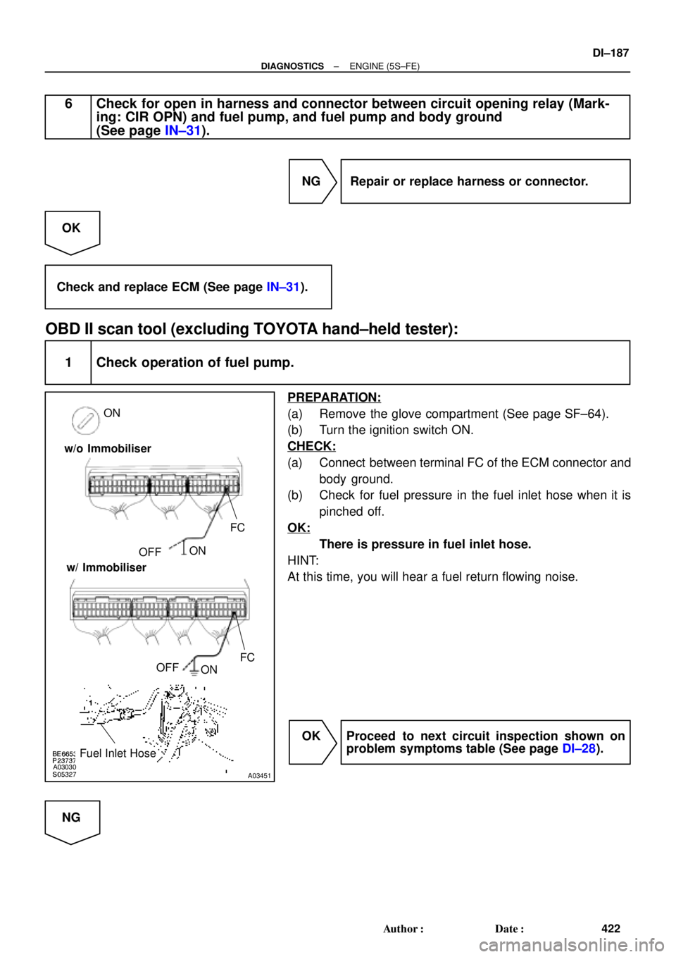
1 Check operation of fuel pump.
PREPARATION:
(a) Remove the glove compartment (See page SF±64).
(b) Turn the ignition switch ON.
CHECK:
(a) Connect between terminal FC of the ECM connector and
body ground.
(b) Check for fuel pressure in the fuel inlet hose when it is
pinched off.
OK:
There is pressure in fuel inlet hose.
HINT:
At this time, you will hear a fuel return flowing noise.
OK Proceed to next circuit inspection shown on
problem symptoms table (See page DI±28).
NG
Page 2608 of 4770
DI±188
± DIAGNOSTICSENGINE (5S±FE)
423 Author�: Date�:
2 Check for ECM power source circuit (See page DI±179).
NG Repair or replace.
OK
3 Check circuit opening relay (Marking: CIR OPN) (See page SF±41).
NG Replace circuit opening relay.
OK
4 Check voltage between terminal FC of ECM connector and body ground
(See page DI±183, step 4).
OK Go to step 5.
NG
Check for open in harness and connector between EFI main relay and circuit opening relay, and
circuit opening relay and ECM (See page IN±31).
5 Check fuel pump (See page SF±6).
NG Repair or replace fuel pump.
OK
Page 2609 of 4770
± DIAGNOSTICSENGINE (5S±FE)
DI±189
424 Author�: Date�:
6 Check for open in harness and connector between circuit opening relay (Mark-
ing: CIR OPN) and fuel pump, and fuel pump and body ground
(See page IN±31).
NG Repair or replace harness or connector.
OK
Check and replace ECM (See page IN±31).
Page 2610 of 4770
A03610
9
W±L
IK2
E9 10
II3
E9 18
LOCK IN
E1 14
EC
BRJ23
IK2 10
BR 1
2A/C Compressor
Lock SensorECM
BR W±L W±L
B
B BRJ/C
AA
A
BR
II3 J8
6J/C
*1: w/o Immobiliser
*2: w/ Immobiliser(*1) (*2)
E919
BR
E9 24
(*1) (*2)
DI±190
± DIAGNOSTICSENGINE (5S±FE)
425 Author�: Date�:
A/C Compressor Lock Sencor Circuit
CIRCUIT DESCRIPTION
This sensor sends 1 pulse par engine revolution to the ECM. If the number ratio of the compressor speed
divided by the engine speed is smaller than a predetermined value, the ECM turns the compressor off. And,
the indicator flashes at about 1 second intervals.
WIRING DIAGRAM
INSPECTION PROCEDURE
1 Check compressor.
PREPARATION:
(a) Check the compressor drive belt tension (See page AC±16).
(b) Check if the compressor does not lock during operation with the engine started and blower switch and
A/C switch ON.
NG Adjust drive belt tension or repair compressor
(See page AC±17).
OK
DI01N±04
Page 2611 of 4770
N15622
12
N02774
LOCK IN Signal Waveform
20 msec./Division (Idling) 0 V
0.2 V/Div.
± DIAGNOSTICSENGINE (5S±FE)
DI±191
426 Author�: Date�:
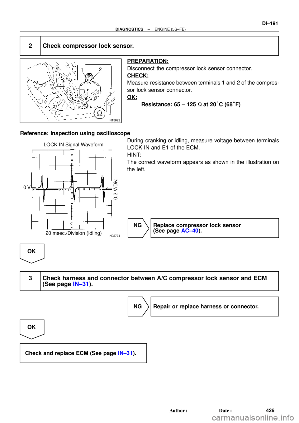
2 Check compressor lock sensor.
PREPARATION:
Disconnect the compressor lock sensor connector.
CHECK:
Measure resistance between terminals 1 and 2 of the compres-
sor lock sensor connector.
OK:
Resistance: 65 ± 125 W at 20°C (68°F)
Reference: Inspection using oscilloscope
During cranking or idling, measure voltage between terminals
LOCK IN and E1 of the ECM.
HINT:
The correct waveform appears as shown in the illustration on
the left.
NG Replace compressor lock sensor
(See page AC±40).
OK
3 Check harness and connector between A/C compressor lock sensor and ECM
(See page IN±31).
NG Repair or replace harness or connector.
OK
Check and replace ECM (See page IN±31).
Page 2613 of 4770

THR (+)
w/o Immobiliser
w/ Immobiliser
E1 (±)THR (+)
AC0175
Thermometer
Ice
Ohmmeter
Thermistor
More than
10 cm (3.94 in.)
± DIAGNOSTICSENGINE (5S±FE)
DI±193")
BE3840
I00180
A03031A03452
ON
E1 (±)
THR (+)
w/o Immobiliser
w/ Immobiliser
E1 (±)THR (+)
AC0175
Thermometer
Ice
Ohmmeter
Thermistor
More than
10 cm (3.94 in.)
± DIAGNOSTICSENGINE (5S±FE)
DI±193
428 Author�: Date�:
INSPECTION PROCEDURE
1 Check voltage between terminals THR and E2 of ECM connector.
PREPARATION:
(a) Remove the glove compartment (See page SF±64).
(b) Turn the ignition switch ON.
CHECK:
Measure voltage between terminals THR and E1 of the ECM
connector at each temperature.
OK:
Voltage
at 0°C (32 F): 2.2 ± 2.6 V
at 15°C (59°F): 1.4 ± 1.8 V
HINT:
As the temperature increases, the voltage decreases.
OK Check and replace ECM (See page IN±31).
NG
2 Check A/C evaporator temp. sensor.
PREPARATION:
Remove the A/C evaporator temp. sensor
(See page AC±30).
CHECK:
Check resistance between terminals 1 and 2 of the A/C evapo-
rator temp. sensor connector at each temperature.
OK:
Resistance
at 0°C (32°F): 4.6 ± 5.1 W
at 15°C (59°F): 2.1 ± 2.6 W
HINT:
As the temperature increases, the voltage decreases.
NG Replace A/C evaporator temp. sensor.
OK
Page 2614 of 4770
DI±194
± DIAGNOSTICSENGINE (5S±FE)
429 Author�: Date�:
3 Check harness and connector between A/C evaporator temp. sensor and ECM
(See page IN±31).
NG Repair or replace harness or connector.
OK
Check and replace ECM (See page IN±31).
Page 2615 of 4770

DI078±08
Vehicle Brought to Workshop
Customer Problem Analysis P. DI±196
Problem Symptom Confirmation
If the engine does not start, perform steps 10 and 12 firstConnect the OBD II scan tool or TOYOTA hand±held tester to DLC3 P. DI±197
If the display indicates a communication fault in the tool, inspect DLC3 P. DI±197
Check DTC and Freezed Frame Data (Precheck)
Record or Print DTC and Freezed Frame Data P. DI±197
Clear DTC and Freezed Frame Data P. DI±197
Visual Inspection
Setting the Check Mode Diagnosis P. DI±197
Symptom Simulation P. IN ± 23
DTC Chart P. DI±211
Problem Symptoms Table P. DI±221
Circuit Inspection P. DI±222
Adjustment, Repair
DTC Check P. DI±197
Titles insideare titles of pages in
in the bottom portion. See the indicated
pages for detailed explanations.this manual with the page number indicated
Malfunction
occurs.Malfunction does not occur.
Parts Inspection
Check for Intermittent Problems P. DI±197
Identification of Problem
Confirmation Test
End 1
2
3
4
5
6
7
108
9
11
12
13
15 14
16
Normal Malfunction code.
17Basic Inspection P. DI±197
± DIAGNOSTICSENGINE (1MZ±FE)
DI±195
430 Author�: Date�:
ENGINE (1MZ±FE)
HOW TO PROCEED WITH TROUBLESHOOTING
Troubleshoot in accordance with the procedure on the following page.


 (*2)
E919
BR
E")