Page 2594 of 4770
A03026A03448
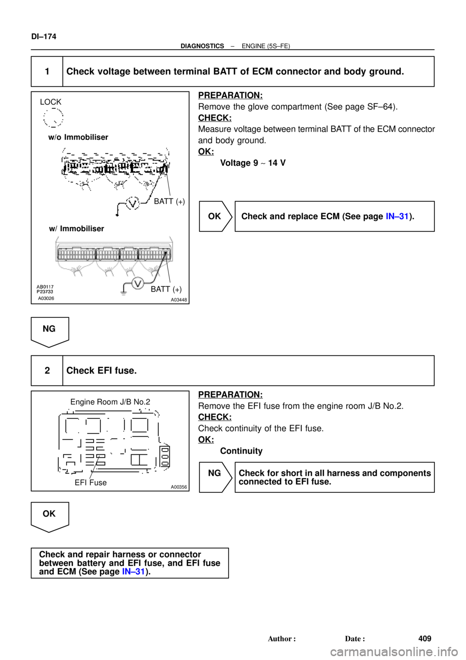
LOCK
BATT (+) w/o Immobiliser
w/ Immobiliser
BATT (+)
A00356
Engine Room J/B No.2
EFI Fuse
DI±174
± DIAGNOSTICSENGINE (5S±FE)
409 Author�: Date�:
1 Check voltage between terminal BATT of ECM connector and body ground.
PREPARATION:
Remove the glove compartment (See page SF±64).
CHECK:
Measure voltage between terminal BATT of the ECM connector
and body ground.
OK:
Voltage 9 ~ 14 V
OK Check and replace ECM (See page IN±31).
NG
2 Check EFI fuse.
PREPARATION:
Remove the EFI fuse from the engine room J/B No.2.
CHECK:
Check continuity of the EFI fuse.
OK:
Continuity
NG Check for short in all harness and components
connected to EFI fuse.
OK
Check and repair harness or connector
between battery and EFI fuse, and EFI fuse
and ECM (See page IN±31).
Page 2597 of 4770
± DIAGNOSTICSENGINE (5S±FE)
DI±177
412 Author�: Date�:
INSPECTION PROCEDURE
HINT:
This diagnostic chart is based on the premise that the engine is cranked normally. If the engine is not
cranked, proceed to the problem symptoms table on page DI±28.
TOYOTA hand±held tester:
1 Connect TOYOTA hand±held tester, and check STA signal.
PREPARATION:
(a) Connect the TOYOTA hand±held tester to the DLC3.
(b) Turn the ignition switch ON and push the TOYOTA hand±held tester main switch ON.
CHECK:
Read STA signal on the TOYOTA hand±held tester while the starter operates.
OK:
Ignition Switch PositionONSTART
STA signalOFFON
OK Proceed to next circuit inspection shown on
problem symptoms table (See page DI±28).
NG
2 Check for open in harness and connector between ECM and starter relay
(Marking: ST) (See page IN±31).
NG Repair or replace harness or connector.
OK
Check and replace ECM (See page IN±31).
Page 2598 of 4770
A03027A03449
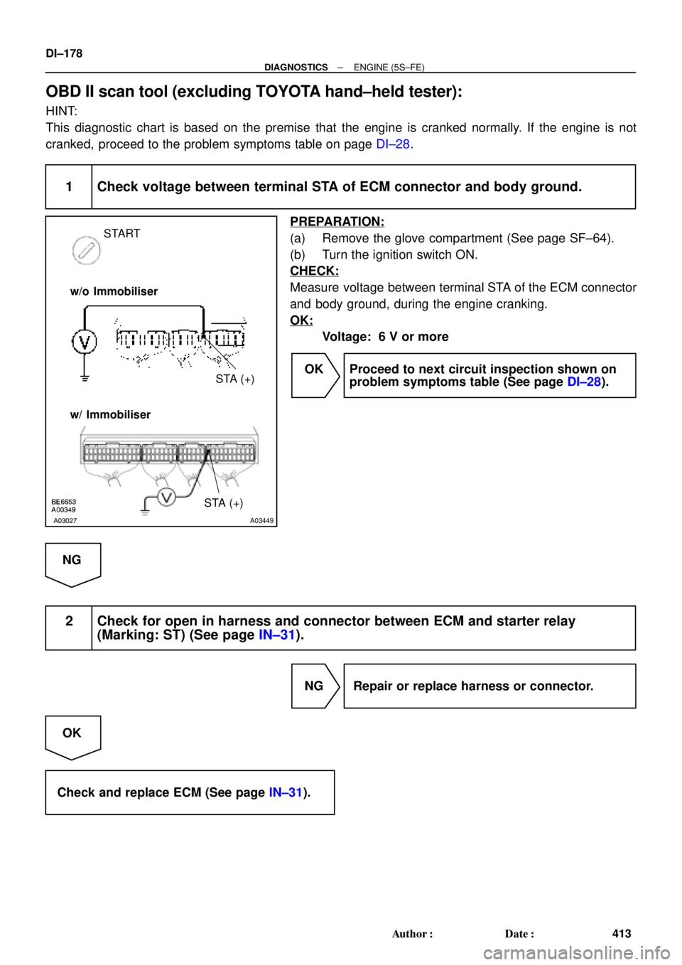
START
STA (+) w/o Immobiliser
w/ Immobiliser
STA (+)
DI±178
± DIAGNOSTICSENGINE (5S±FE)
413 Author�: Date�:
OBD II scan tool (excluding TOYOTA hand±held tester):
HINT:
This diagnostic chart is based on the premise that the engine is cranked normally. If the engine is not
cranked, proceed to the problem symptoms table on page DI±28.
1 Check voltage between terminal STA of ECM connector and body ground.
PREPARATION:
(a) Remove the glove compartment (See page SF±64).
(b) Turn the ignition switch ON.
CHECK:
Measure voltage between terminal STA of the ECM connector
and body ground, during the engine cranking.
OK:
Voltage: 6 V or more
OK Proceed to next circuit inspection shown on
problem symptoms table (See page DI±28).
NG
2 Check for open in harness and connector between ECM and starter relay
(Marking: ST) (See page IN±31).
NG Repair or replace harness or connector.
OK
Check and replace ECM (See page IN±31).
Page 2600 of 4770
BE6653
A03028
A03709
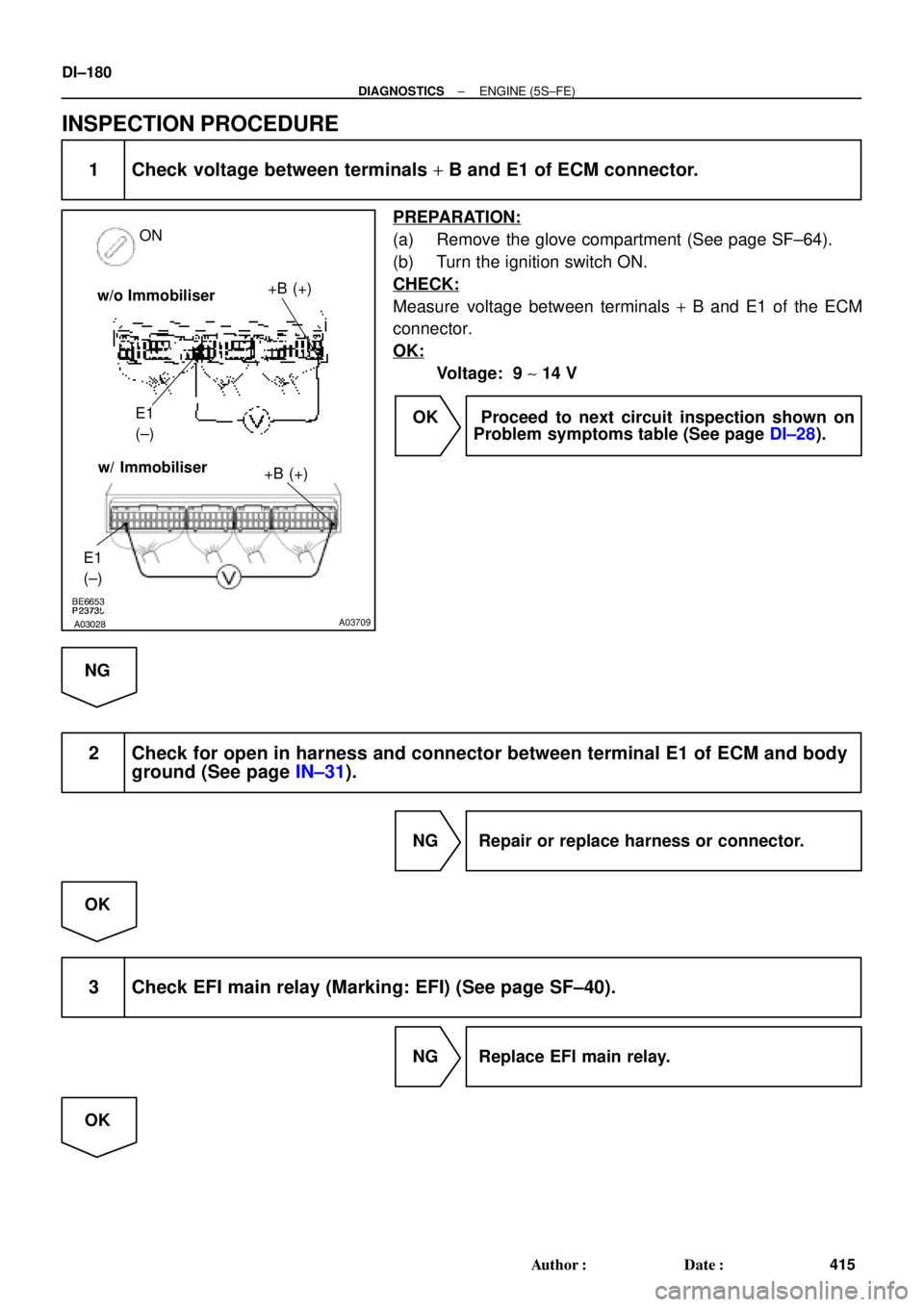
ON
+B (+)
E1
(±)
E1
(±)
+B (+)w/ Immobiliser w/o Immobiliser
DI±180
± DIAGNOSTICSENGINE (5S±FE)
415 Author�: Date�:
INSPECTION PROCEDURE
1 Check voltage between terminals + B and E1 of ECM connector.
PREPARATION:
(a) Remove the glove compartment (See page SF±64).
(b) Turn the ignition switch ON.
CHECK:
Measure voltage between terminals + B and E1 of the ECM
connector.
OK:
Voltage: 9 ~ 14 V
OK Proceed to next circuit inspection shown on
Problem symptoms table (See page DI±28).
NG
2 Check for open in harness and connector between terminal E1 of ECM and body
ground (See page IN±31).
NG Repair or replace harness or connector.
OK
3 Check EFI main relay (Marking: EFI) (See page SF±40).
NG Replace EFI main relay.
OK
Page 2601 of 4770
A00355
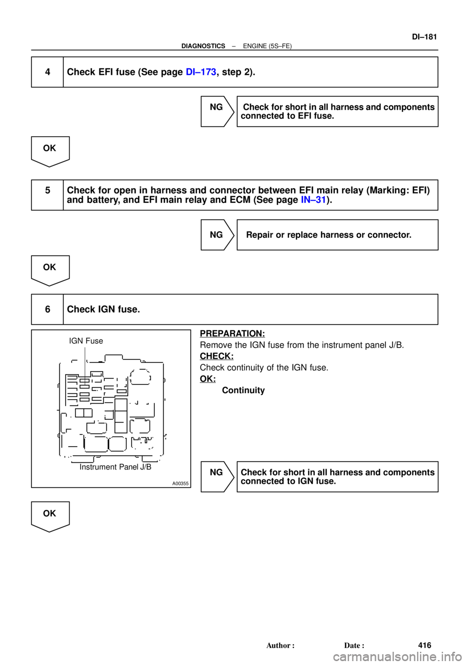
IGN Fuse
Instrument Panel J/B
± DIAGNOSTICSENGINE (5S±FE)
DI±181
416 Author�: Date�:
4 Check EFI fuse (See page DI±173, step 2).
NG Check for short in all harness and components
connected to EFI fuse.
OK
5 Check for open in harness and connector between EFI main relay (Marking: EFI)
and battery, and EFI main relay and ECM (See page IN±31).
NG Repair or replace harness or connector.
OK
6 Check IGN fuse.
PREPARATION:
Remove the IGN fuse from the instrument panel J/B.
CHECK:
Check continuity of the IGN fuse.
OK:
Continuity
NG Check for short in all harness and components
connected to IGN fuse.
OK
Page 2602 of 4770
DI±182
± DIAGNOSTICSENGINE (5S±FE)
417 Author�: Date�:
7 Check ignition switch (See page BE±14).
NG Replace ignition switch.
OK
Check for open in harness and connector between IG switch and EFI main relay, and EFI main
relay and body ground (See page IN±31).
Page 2605 of 4770
± DIAGNOSTICSENGINE (5S±FE)
DI±185
420 Author�: Date�:
INSPECTION PROCEDURE
TOYOTA hand±held tester:
1 Connect TOYOTA hand±held tester, and check operation of fuel pump
(See page DI±3).
OK Proceed to next circuit inspection shown on
problem symptoms table (See page DI±28).
NG
2 Check for ECM power source circuit (See page DI±179).
NG Repair or replace.
OK
3 Check circuit opening relay (Marking: CIR OPN) (See page SF±41).
NG Replace circuit opening relay.
OK
Page 2606 of 4770
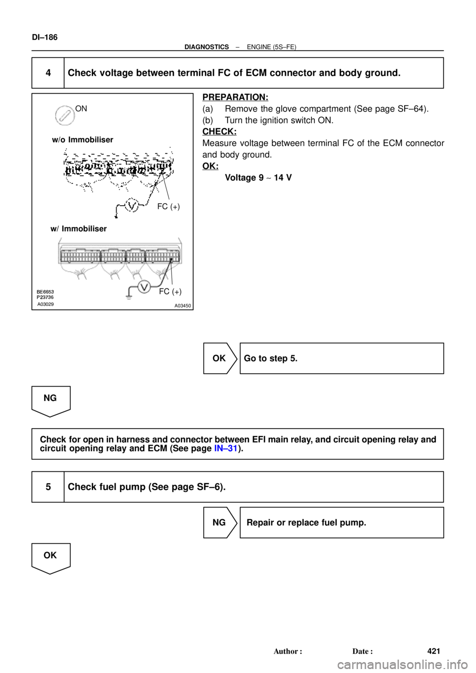
A03029A03450
FC (+) ON
w/o Immobiliser
w/ Immobiliser
FC (+)
DI±186
± DIAGNOSTICSENGINE (5S±FE)
421 Author�: Date�:
4 Check voltage between terminal FC of ECM connector and body ground.
PREPARATION:
(a) Remove the glove compartment (See page SF±64).
(b) Turn the ignition switch ON.
CHECK:
Measure voltage between terminal FC of the ECM connector
and body ground.
OK:
Voltage 9 ~ 14 V
OK Go to step 5.
NG
Check for open in harness and connector between EFI main relay, and circuit opening relay and
circuit opening relay and ECM (See page IN±31).
5 Check fuel pump (See page SF±6).
NG Repair or replace fuel pump.
OK