Page 2582 of 4770
DI±162
± DIAGNOSTICSENGINE (5S±FE)
397 Author�: Date�:
2 Check resistance of A/F sensor heater (See page SF±59).
NG Replace A/F sensor.
OK
Check and repair harness or connector between EFI main relay (Marking: EFI) and A/F sensor,
and A/F sensor and ECM (See page IN±31).
Page 2584 of 4770

A07122
IG Switch
B±R
BatteryEngine Room
J/B No.2
76B±R13
1II3B±R
B
BR
Spark Plug
Spark Plug
2
3 2
3 4
Tr2 Igniter
No.1
Ignition
Coil
No.1
FL Block
Y±R
BR
B
20
19
IGT2
Tr1
E9
E9
E9
W±R
IGT1
IGF5 V
Tr1
Ignition Coil
No.2
Igniter
No.2
AA A
EC
Tr2
W±R
B±R 5 51B 1K
Instrument
W±R
W±R
2L 2A
4 1
AM2B
F4 F6 1
1
B±G
MAIN FL
3 1
4
J/C J25
*1: w/o Immobiliser
*2: w/ Immobiliser(*1) (*2)
ECM
E9 23
E9 22
E9 17
(*1) (*2)
W±R
Panel J/BB
B
BR
BR J19
J/C
DI±164
± DIAGNOSTICSENGINE (5S±FE)
399 Author�: Date�:
WIRING DIAGRAM
INSPECTION PROCEDURE
HINT:
�If DTC P1300 is displayed, check ignition coil No.1 circuit.
�If DTC P1300 is displayed, check ignition coil No.2 circuit.
�Read freeze frame data using TOYOTA hand±held tester or OBD II scan tool. Because freeze frame
records the engine conditions when the malfunction is detected, when troubleshooting it is useful for
determining whether the vehicle was running or stopped, the engine warmed up or not, the air±fuel
ratio lean or rich, etc. at the time of the malfunction.
1 Check for spark plug and spark of misifining cylinder (See page DI±89).
NG Go to step 4.
OK
2 Check for open and short in harness and connector in IGF signal circuit between
ECM and ignition coils (See page IN±31).
NG Repair or replace harness or connector.
OK
Page 2585 of 4770
A03023A00417A03427
ON
IGF
(+)
w/o Immobiliser
w/ Immobiliser
IGF
(+)
± DIAGNOSTICSENGINE (5S±FE)
DI±165
400 Author�: Date�:
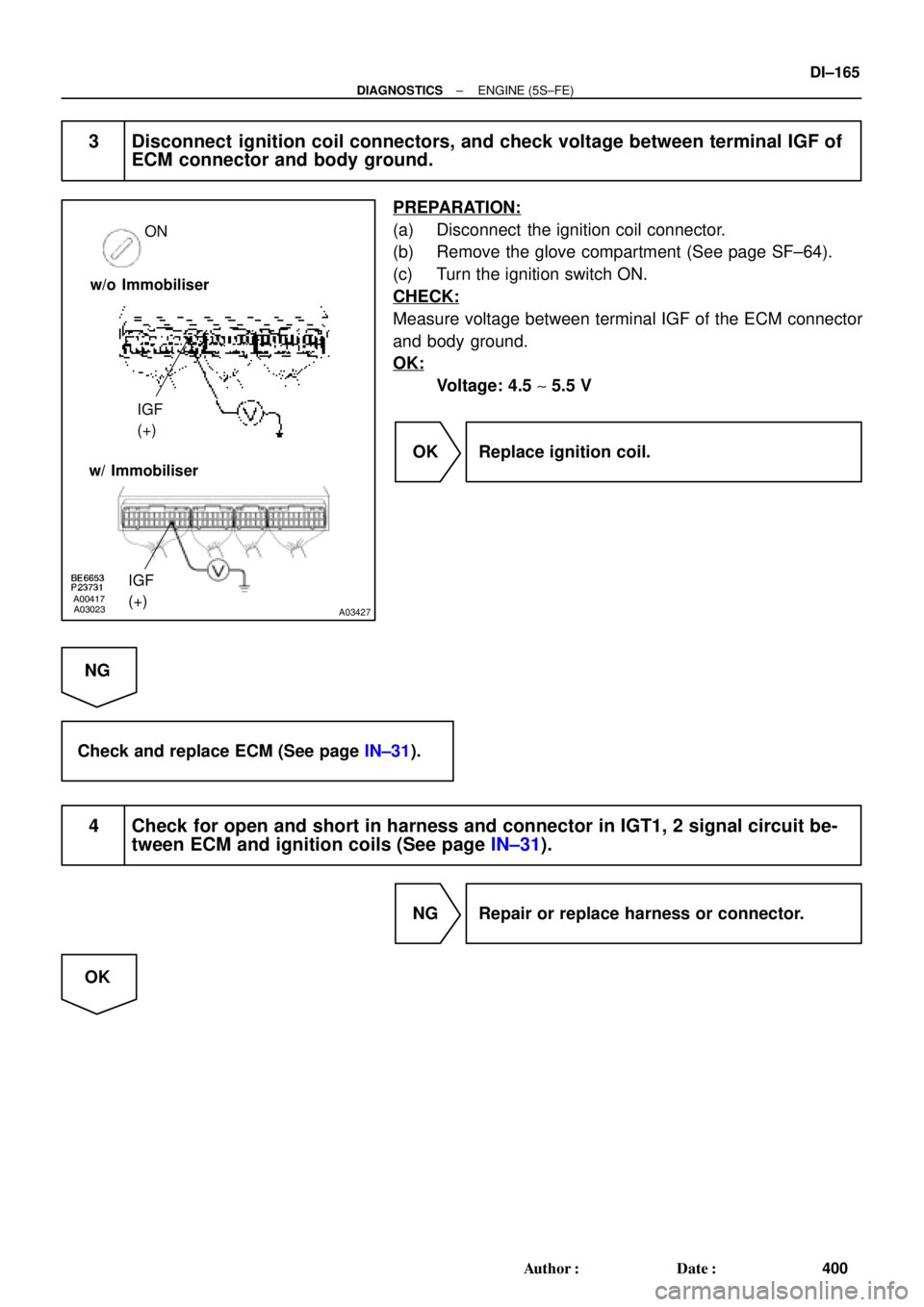
3 Disconnect ignition coil connectors, and check voltage between terminal IGF of
ECM connector and body ground.
PREPARATION:
(a) Disconnect the ignition coil connector.
(b) Remove the glove compartment (See page SF±64).
(c) Turn the ignition switch ON.
CHECK:
Measure voltage between terminal IGF of the ECM connector
and body ground.
OK:
Voltage: 4.5 ~ 5.5 V
OK Replace ignition coil.
NG
Check and replace ECM (See page IN±31).
4 Check for open and short in harness and connector in IGT1, 2 signal circuit be-
tween ECM and ignition coils (See page IN±31).
NG Repair or replace harness or connector.
OK
Page 2586 of 4770
A03024A03428
START
IGT2 (+)
IGT1 (+)
IGT2 (+)
IGT1 (+) w/o Immobiliser
w/ Immobiliser
FI6680
IGT Signal Waveform
10 msec./Division (Idling) IGT
0 V
IGF
0 V2 V/
Division
DI±166
± DIAGNOSTICSENGINE (5S±FE)
401 Author�: Date�:
5 Check voltage between terminals IGT1, 2 of ECM connector and body ground.
PREPARATION:
Remove the glove compartment (See page SF±64).
CHECK:
Measure voltage between terminal IGT1, 2 of the ECM connec-
tor and body ground when the engine is cranked.
OK:
Voltage: More than 0.1 V and less than 4.5 V
Reference: INSPECTION USING OSCILLOSCOPE
During idling, check waveform between terminals IGT1, 2 and
E1 of the ECM.
HINT:
The correct waveforms are as shown.
NG Check and replace ECM (See page IN±31).
NG
Page 2587 of 4770
A03024A03428
START
IGT2 (+)
IGT1 (+)
w/o Immobiliser
w/ Immobiliser
IGT2 (+)
IGT1 (+)
BE6653A01761A01861
ON
START
1 (+)
± DIAGNOSTICSENGINE (5S±FE)
DI±167
402 Author�: Date�:
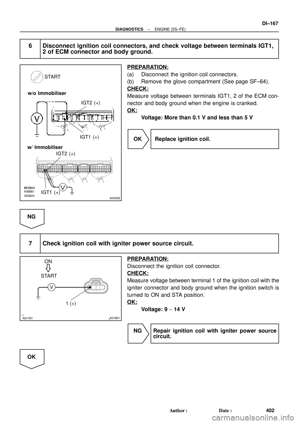
6 Disconnect ignition coil connectors, and check voltage between terminals IGT1,
2 of ECM connector and body ground.
PREPARATION:
(a) Disconnect the ignition coil connectors.
(b) Remove the glove compartment (See page SF±64).
CHECK:
Measure voltage between terminals IGT1, 2 of the ECM con-
nector and body ground when the engine is cranked.
OK:
Voltage: More than 0.1 V and less than 5 V
OK Replace ignition coil.
NG
7 Check ignition coil with igniter power source circuit.
PREPARATION:
Disconnect the ignition coil connector.
CHECK:
Measure voltage between terminal 1 of the ignition coil with the
igniter connector and body ground when the ignition switch is
turned to ON and STA position.
OK:
Voltage: 9 ~ 14 V
NG Repair ignition coil with igniter power source
circuit.
OK
Page 2588 of 4770
DI±168
± DIAGNOSTICSENGINE (5S±FE)
403 Author�: Date�:
8 Check for open and short in harness and connector between ignition switch and
ignition coils (See page IN±31).
NG Repair or replace harness or connector.
OK
9 Check ignition coil (See page IG±5).
NG Replace ignition coil.
OK
10 Check EFI main relay (Marking: EFI) (See page SF±40).
NG Replace EFI main relay.
OK
Replace igniter.
Page 2591 of 4770
± DIAGNOSTICSENGINE (5S±FE)
DI±171
406 Author�: Date�:
INSPECTION PROCEDURE
HINT:
Read freeze frame data using TOYOTA hand±held tester or OBD II scan tool. Because freeze frame records
the engine conditions when the malfunction is detected, when troubleshooting it is useful for determining
whether the vehicle was running or stopped, the engine warmed up or not, the air±fuel ratio lean or rich, etc.
at the time of the malfunction.
1 Check operation of stop light.
PREPARATION:
Check if the stop lights go on and off normally when the brake pedal is operated and released.
NG Check and repair stop light circuit
(See page BE±37).
OK
Page 2592 of 4770
A03025A03429
Brake Pedal
Depressed
ON ON
STP (+) Brake Pedal
Released
w/o Immobiliser
w/ Immobiliser
STP (+)
DI±172
± DIAGNOSTICSENGINE (5S±FE)
407 Author�: Date�:
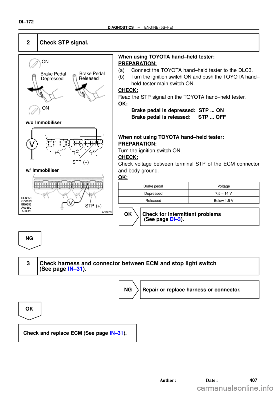
2 Check STP signal.
When using TOYOTA hand±held tester:
PREPARATION:
(a) Connect the TOYOTA hand±held tester to the DLC3.
(b) Turn the ignition switch ON and push the TOYOTA hand±
held tester main switch ON.
CHECK:
Read the STP signal on the TOYOTA hand±held tester.
OK:
Brake pedal is depressed: STP ... ON
Brake pedal is released: STP ... OFF
When not using TOYOTA hand±held tester:
PREPARATION:
Turn the ignition switch ON.
CHECK:
Check voltage between terminal STP of the ECM connector
and body ground.
OK:
Brake pedalVoltage
Depressed7.5 ~ 14 V
ReleasedBelow 1.5 V
OK Check for intermittent problems
(See page DI±3).
NG
3 Check harness and connector between ECM and stop light switch
(See page IN±31).
NG Repair or replace harness or connector.
OK
Check and replace ECM (See page IN±31).


IGT1 (+)
IGT2 (+)
IGT1 (+) w/o Immobiliser
w/ Immobiliser
FI6680
IGT Signal Waveform
10 msec./Division (Idling) IGT
0 V
IGF
0 V2 V/
Division
DI±166
± DIAGNOSTICSENGINE (5")