Page 3454 of 4770
CYLINDER HEAD
1234 Author�: Date�:
25. INSTALL IGNITION COILS AND NO.2 INTAKE MAN-
IFOLD STAY ASSEMBLY
(a) TM")
S05548
Wire
Clamp
S05297
Clamp
Sensor
Connector
S05281
EM±62
± ENGINE MECHANICAL (5S±FE)CYLINDER HEAD
1234 Author�: Date�:
25. INSTALL IGNITION COILS AND NO.2 INTAKE MAN-
IFOLD STAY ASSEMBLY
(a) TMC Made:
Install the 2 ignition coils and manifold stay assembly with
the 2 nuts and 2 bolts.
Torque:
21 N´m (214 kgf´cm, 15 ft´lbf) for 12 mm head
42 N´m (428 kgf´cm, 31 ft´lbf) for 14 mm head
(b) TMMK Made:
Install the 2 ignition coils and manifold stay assembly with
the nut and 3 bolts.
Torque:
21 N´m (214 kgf´cm, 15 ft´lbf) for 12 mm head
42 N´m (428 kgf´cm, 31 ft´lbf) for 14 mm head
(c) Install the wire clamp to the manifold stay.
(d) Connect the 4 high±tension cords to the spark plugs.
(e) Install the 4 high±tension cords to the 2 clamps on the cyl-
inder head cover.
(f) Connect the 2 ignition coil connectors.
26. INSTALL THROTTLE BODY (See page SF±34)
27. INSTALL EXHAUST MANIFOLD
(a) California:
Install the A/F sensor connector for the wiring side to the
bracket to the LH engine hanger.
(b) Except California:
Install the heated oxygen sensor for the wiring side to the
bracket to the LH engine hanger.
(c) Attach the exhaust manifold to the front exhaust pipe.
(d) Install a new gasket, the exhaust manifold, No.2 and No.3
exhaust manifold heat insulators assembly with the 6
nuts. Uniformly tighten the nuts in several passes.
Torque: 49 N´m (500 kgf´cm, 36 ft´lbf)
(e) Install the wire clamp.
(f) California:
Connect the A/F sensor connector.
(g) Except California:
Connect the heated oxygen sensor (bank 1 sensor 1)
connector.
(h) Install the No.1 exhaust manifold stay with the 2 bolts.
Torque: 42 N´m (425 kgf´cm, 31 ft´lbf)
Page 3461 of 4770
ENGINE UNIT
EM±69
1241 Author�: Date�:
REMOVAL
1. REMOVE HOOD
2. REMOVE FRONT FENDER APRON SEALS
3. DRAIN ENGINE COOLANT
4. DRAIN ENGINE OIL
5. DISCONNEC")
EM08F±04
S05251
± ENGINE MECHANICAL (5S±FE)ENGINE UNIT
EM±69
1241 Author�: Date�:
REMOVAL
1. REMOVE HOOD
2. REMOVE FRONT FENDER APRON SEALS
3. DRAIN ENGINE COOLANT
4. DRAIN ENGINE OIL
5. DISCONNECT ACCELERATOR CABLE
6. REMOVE AIR CLEANER CAP
(a) Disconnect the IAT sensor connector.
(b) Disconnect the VSV connector for the EVAP
(c) Disconnect the PCV hose from the cylinder head cover.
(d) Disconnect the EVAP hose from the throttle body.
(e) Disconnect the EVAP hose from the VSV.
(f) Disconnect the 2 clamps, and disconnect the air cleaner
cap from the air cleaner case.
(g) Loosen hose clamp, and disconnect the air cleaner hose
from the throttle body.
(h) Remove the air cleaner cap and hose assembly.
7. REMOVE AIR CLEANER CASE
(a) Remove the air filter.
(b) Remove the 3 bolts and air cleaner case.
8. REMOVE BATTERY AND TRAY
9. REMOVE CRUISE CONTROL ACTUATOR
10. REMOVE RADIATOR (See page CO±18)
11. REMOVE FRONT EXHAUST PIPE
(a) Remove the 2 bolts holding the support stay to the sup-
port bracket.
(b) Remove the 2 bolts holding the support bracket to the
front frame.
(c) Remove the 2 bolts and 2 nuts holding the front exhaust
pipe to the center exhaust pipe.
(d) Remove the 3 nuts holding the front exhaust pipe to the
exhaust manifold.
(e) Remove the front exhaust pipe and 2 gaskets.
(f) Remove the nut and support bracket.
12. DISCONNECT CONNECTORS, WIRES, CABLES,
CLAMPS AND HOSES
(a) Disconnect the generator wire.
(b) Disconnect the generator connector.
(c) Disconnect the wire clamp from the generator.
(d) Disconnect the starter cable.
(e) Disconnect the starter connector.
(f) Disconnect the DLC1 from the bracket.
Page 3462 of 4770
ENGINE UNIT
1242 Author�: Date�:
(g) Disconnect the engine wire clamp from the bracket on the
RH fender apron.
(h) Disconnect the MAP sensor connector.
(i)")
S05253
EM±70
± ENGINE MECHANICAL (5S±FE)ENGINE UNIT
1242 Author�: Date�:
(g) Disconnect the engine wire clamp from the bracket on the
RH fender apron.
(h) Disconnect the MAP sensor connector.
(i) Disconnect the wire clamp from the bracket for the MAP
sensor.
(j) Disconnect the 2 ground strap connectors from the RH
fender apron.
(k) Disconnect the 2 ground strap connectors from the LH
fender apron.
(l) Disconnect the engine wire protector clamp from the bat-
tery bracket.
(m) Disconnect the engine wire from the clamp on the fuel fil-
ter.
(n) Disconnect the ground cable from the transaxle.
(o) Disconnect the brake booster vacuum hose from the in-
take manifold.
(p) Disconnect the heater hose from the water outlet.
(q) Disconnect the heater hose from the water bypass pipe.
(r) Disconnect the fuel inlet hose from the fuel filter.
(s) Disconnect the MAP sensor vacuum hose from the gas
filter on the intake manifold.
13. DISCONNECT ENGINE WIRE FROM CABIN
(a) Remove the under cover.
(b) Disconnect the 3 ECM connectors.
(c) Disconnect the 3 cowl wire connectors from the connec-
tors on the bracket.
(d) Disconnect the grommet from the cowl panel, and pull out
the engine wire.
14. REMOVE DRIVE SHAFTS (See page SA±17)
15. DISCONNECT TRANSAXLE CONTROL CABLE(S)
FROM TRANSAXLE
16. M/T:
REMOVE STARTER (See page ST±5)
17. M/T:
DISCONNECT CLUTCH RELEASE CYLINDER AND
TUBE FROM TRANSAXLE
Page 3471 of 4770
ENGINE UNIT
EM±79
1251 Author�: Date�:
A/T:
Install the 4 bolts.
Torque: 64 N´m (650 kgf´cm, 47 ft´lbf)
24. REMOVE ENGINE SLI")
S04616
A/T
S05246
S05250
Connector
S05253
± ENGINE MECHANICAL (5S±FE)ENGINE UNIT
EM±79
1251 Author�: Date�:
A/T:
Install the 4 bolts.
Torque: 64 N´m (650 kgf´cm, 47 ft´lbf)
24. REMOVE ENGINE SLING DEVICE
25. CONNECT TRANSAXLE CONTROL CABLE(S) TO
TRANSAXLE
26. INSTALL PS PUMP
(a) Install the PS pump with the 2 bolts.
Torque: 43 N´m (440 kgf´cm, 32 ft´lbf)
(b) Install the drive belt.
(c) Connect the PS oil pressure switch connector.
27. INSTALL A/C COMPRESSOR
(a) Install the cylinder block insulator and A/C compressor
with the 3 bolts.
Torque: 25.5 N´m (260 kgf´cm, 19 ft´lbf)
(b) Install the drive belt.
(c) Connect the A/C compressor connector.
28. M/T:
INSTALL CLUTCH RELEASE CYLINDER AND TUBE
TO TRANSAXLE
29. M/T:
INSTALL STARTER (See page ST±19)
30. INSTALL DRIVE SHAFTS (See page SA±24)
31. CONNECT ENGINE WIRE TO CABIN
(a) Push in the engine wire through the cowl panel. Install the
grommet.
(b) Connect the 3 engine ECM connectors.
(c) Connect the 3 cowl wire connectors to the connectors on
the bracket.
(d) Install the under cover.
32. CONNECT CONNECTORS, WIRES, CABLES,
CLAMPS AND HOSES
(a) Connect the generator wire.
Page 3473 of 4770
± ENGINE MECHANICAL (5S±FE)ENGINE UNIT
EM±81
1253 Author�: Date�:
38. INSTALL AIR CLEANER CAP
(a) Connect the air cleaner hose to the throttle body.
(b) Attach the air cleaner cap to the air cleaner case, and
install the 2 clamps.
(c) Tighten the air cleaner hose clamp.
(d) Connect the PCV hose to the cylinder head cover.
(e) Connect the EVAP hose to the throttle body.
(f) Connect the EVAP hose to the VSV.
(g) Connect the IAT sensor connector.
(h) Connect the VSV connector for the EVAP.
39. CONNECT ACCELERATOR CABLE
40. INSTALL ENGINE FENDER APRON SEALS
41. INSTALL HOOD
42. FILL ENGINE WITH OIL
43. FILL WITH ENGINE COOLANT
44. START ENGINE AND CHECK FOR LEAKS
45. RECHECK ENGINE COOLANT AND OIL LEVELS
Page 3474 of 4770
EM08H±03
A07366
No.2 Timing Belt
Cover
No.1 Timing Belt
Cover
Crankshaft
Pulley
No.2 Idler PulleyTension Spring* Gasket
Timing Belt Guide Timing Belt
High±Tension Cord
Spark Plug
N´m (kgf´cm, ft´lbf)Wire
ClampGenerator
Wire Clamp
Crankshaft Timing Pulley
Camshaft Timing Pulley
No.1 Idler PulleyWire ClampWire Clamp
108 (1,100, 80)
54 (550, 40)
42 (425, 31)
18 (180, 13)
42 (425, 31)
: Specified torque* Gasket
* Replace only if damaged
EM±82
± ENGINE MECHANICAL (5S±FE)CYLINDER BLOCK
1254 Author�: Date�:
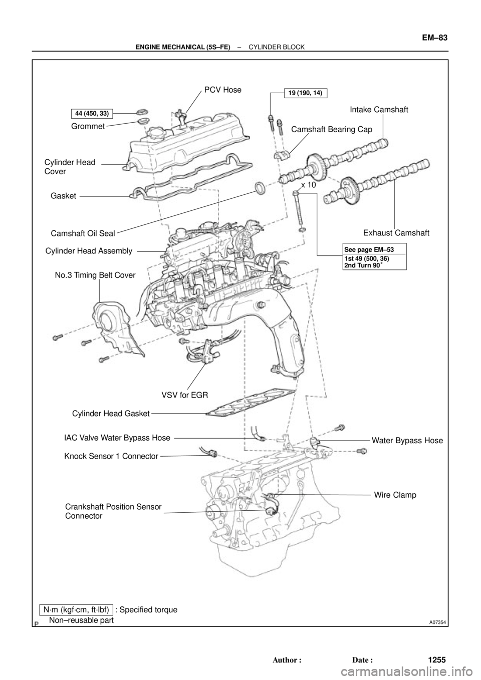
CYLINDER BLOCK
COMPONENTS
Page 3475 of 4770
A07354
Grommet
Cylinder Head
Cover
Gasket
� Camshaft Oil Seal
Cylinder Head Assembly
No.3 Timing Belt Cover
Crankshaft Position Sensor
ConnectorWire Clamp Water Bypass Hose Exhaust Camshaft Intake Camshaft
Camshaft Bearing Cap PCV Hose
� Cylinder Head Gasket
IAC Valve Water Bypass Hose
Knock Sensor 1 Connector
N´m (kgf´cm, ft´lbf)
� Non±reusable part
44 (450, 33)
19 (190, 14)
VSV for EGR
: Specified torquex 10
1st 49 (500, 36)
2nd Turn 90° See page EM±53
± ENGINE MECHANICAL (5S±FE)CYLINDER BLOCK
EM±83
1255 Author�: Date�:
Page 3478 of 4770
CYLINDER BLOCK
1258 Author�: Date�:
DISASSEMBLY
1. INSTALL ENGINE TO ENGINE STAND FOR DIS-
ASSEMBLY
2. REMOVE TIMING BELT AND PULLEYS
(See pa")
EM0YW±01
S06011
1
3
2 EM±86
± ENGINE MECHANICAL (5S±FE)CYLINDER BLOCK
1258 Author�: Date�:
DISASSEMBLY
1. INSTALL ENGINE TO ENGINE STAND FOR DIS-
ASSEMBLY
2. REMOVE TIMING BELT AND PULLEYS
(See page EM±17)
3. REMOVE CYLINDER HEAD ASSEMBLY
(a) Remove the 3 bolts and No.3 timing belt cover.
(b) Remove the cylinder head cover.
(1) Disconnect the PCV hose from the intake manifold.
(2) Remove the 4 nuts, 4 grommets, head cover and
gasket.
(c) Remove the camshafts. (See page EM±33)
(d) Disconnect the knock sensor 1 connector.
(e) Disconnect the crankshaft position sensor connector.
(f) Disconnect the wire clamp from the generator drive belt
adjusting bar.
(g) Disconnect the IAC valve water bypass hose from the wa-
ter bypass pipe.
(h) Disconnect the water bypass hose (from the water by-
pass pipe) from the water outlet.
(i) Remove the bolt holding the VSV for EGR to the intake
manifold.
(j) Remove the 2 bolts holding the water bypass pipe to the
cylinder head.
(k) Remove the cylinder head assembly.
(See page EM±33)
4. REMOVE OIL DIPSTICK
5. REMOVE OIL PAN AND OIL PUMP
(a) Disconnect the crankshaft position sensor connector
from the generator drive belt adjusting bar.
(b) Remove the oil pan and oil pump. (See page LU±7)
6. REMOVE PS PUMP BRACKET
Remove the 3 bolts and pump bracket.
7. REMOVE KNOCK SENSOR 1 (See page SF±57)
8. REMOVE OIL FILTER (See page LU±2)
9. REMOVE WATER PUMP, WATER BYPASS PIPE AND
OIL COOLER (w/ OIL COOLER) ASSEMBLY
(a) w/ Oil Cooler:
Remove the nut and union bolt, and disconnect the oil
cooler. Remove the O±ring.
(b) Remove the bolt and generator drive belt adjusting bar.
(c) Remove the 3 bolts in the sequence shown, remove the
water pump, water bypass pipe, oil cooler (w/ oil cooler)
assembly and O±ring.