Page 3543 of 4770
P12710
O±Ring
A01816
P12811Align Intake
P12871
Main Gear
Sub±Gear
Service Bolt Intake
± ENGINE MECHANICAL (1MZ±FE)CYLINDER HEAD
EM±37
1323 Author�: Date�:
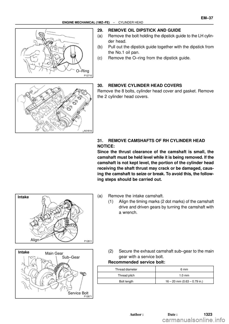
29. REMOVE OIL DIPSTICK AND GUIDE
(a) Remove the bolt holding the dipstick guide to the LH cylin-
der head.
(b) Pull out the dipstick guide together with the dipstick from
the No.1 oil pan.
(c) Remove the O±ring from the dipstick guide.
30. REMOVE CYLINDER HEAD COVERS
Remove the 8 bolts, cylinder head cover and gasket. Remove
the 2 cylinder head covers.
31. REMOVE CAMSHAFTS OF RH CYLINDER HEAD
NOTICE:
Since the thrust clearance of the camshaft is small, the
camshaft must be held level while it is being removed. If the
camshaft is not kept level, the portion of the cylinder head
receiving the shaft thrust may crack or be damaged, caus-
ing the camshaft to seize or break. To avoid this, the follow-
ing steps should be carried out.
(a) Remove the intake camshaft.
(1) Align the timing marks (2 dot marks) of the camshaft
drive and driven gears by turning the camshaft with
a wrench.
(2) Secure the exhaust camshaft sub±gear to the main
gear with a service bolt.
Recommended service bolt:
Thread diameter6 mm
Thread pitch1.0 mm
Bolt length16 ± 20 mm (0.63 ± 0.79 in.)
Page 3570 of 4770
P12812
: Seal Packing
Front
RH Side
LH Side
A06649
Manifold
StayM/T and California A/T
Manifold
Stay
Except M/T and California A/T
P18773
EM±64
± ENGINE MECHANICAL (1MZ±FE)CYLINDER HEAD
1350 Author�: Date�:
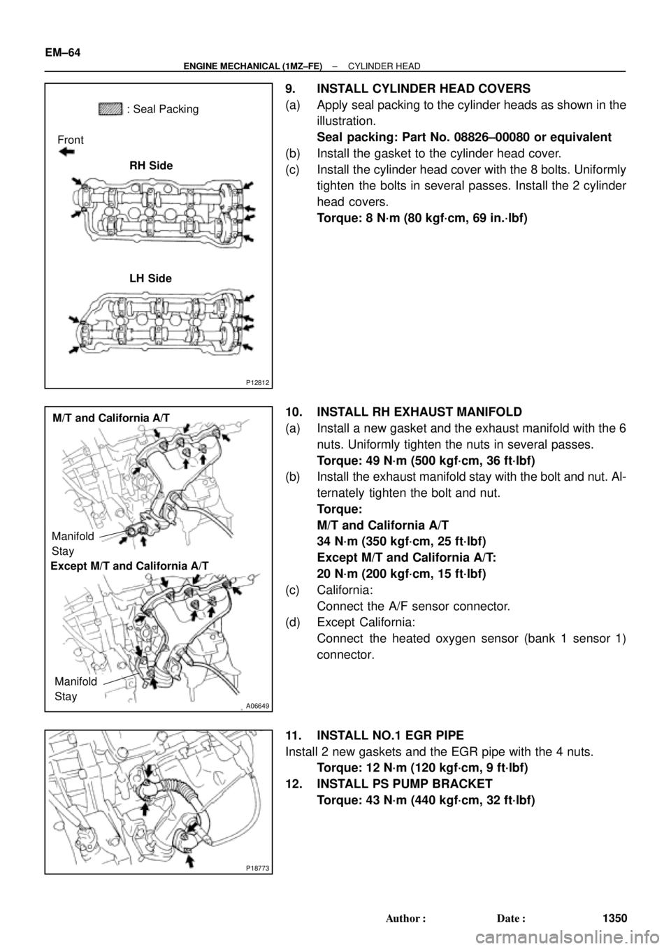
9. INSTALL CYLINDER HEAD COVERS
(a) Apply seal packing to the cylinder heads as shown in the
illustration.
Seal packing: Part No. 08826±00080 or equivalent
(b) Install the gasket to the cylinder head cover.
(c) Install the cylinder head cover with the 8 bolts. Uniformly
tighten the bolts in several passes. Install the 2 cylinder
head covers.
Torque: 8 N´m (80 kgf´cm, 69 in.´lbf)
10. INSTALL RH EXHAUST MANIFOLD
(a) Install a new gasket and the exhaust manifold with the 6
nuts. Uniformly tighten the nuts in several passes.
Torque: 49 N´m (500 kgf´cm, 36 ft´lbf)
(b) Install the exhaust manifold stay with the bolt and nut. Al-
ternately tighten the bolt and nut.
Torque:
M/T and California A/T
34 N´m (350 kgf´cm, 25 ft´lbf)
Except M/T and California A/T:
20 N´m (200 kgf´cm, 15 ft´lbf)
(c) California:
Connect the A/F sensor connector.
(d) Except California:
Connect the heated oxygen sensor (bank 1 sensor 1)
connector.
11. INSTALL NO.1 EGR PIPE
Install 2 new gaskets and the EGR pipe with the 4 nuts.
Torque: 12 N´m (120 kgf´cm, 9 ft´lbf)
12. INSTALL PS PUMP BRACKET
Torque: 43 N´m (440 kgf´cm, 32 ft´lbf)
Page 3571 of 4770
P12710
New O±Ring
A01522
Manifold
Stay California A/T
Manifold Stay
(Except M/T)Except California A/T
S04789
Ground
Strap
Inlet PipeRear
Plate
± ENGINE MECHANICAL (1MZ±FE)CYLINDER HEAD
EM±65
1351 Author�: Date�:
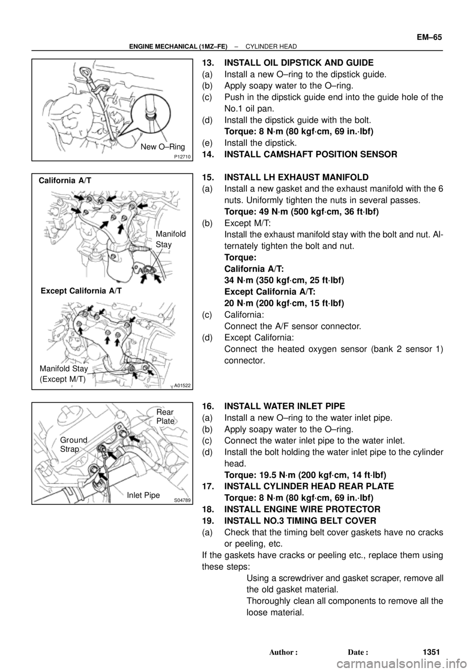
13. INSTALL OIL DIPSTICK AND GUIDE
(a) Install a new O±ring to the dipstick guide.
(b) Apply soapy water to the O±ring.
(c) Push in the dipstick guide end into the guide hole of the
No.1 oil pan.
(d) Install the dipstick guide with the bolt.
Torque: 8 N´m (80 kgf´cm, 69 in.´lbf)
(e) Install the dipstick.
14. INSTALL CAMSHAFT POSITION SENSOR
15. INSTALL LH EXHAUST MANIFOLD
(a) Install a new gasket and the exhaust manifold with the 6
nuts. Uniformly tighten the nuts in several passes.
Torque: 49 N´m (500 kgf´cm, 36 ft´lbf)
(b) Except M/T:
Install the exhaust manifold stay with the bolt and nut. Al-
ternately tighten the bolt and nut.
Torque:
California A/T:
34 N´m (350 kgf´cm, 25 ft´lbf)
Except California A/T:
20 N´m (200 kgf´cm, 15 ft´lbf)
(c) California:
Connect the A/F sensor connector.
(d) Except California:
Connect the heated oxygen sensor (bank 2 sensor 1)
connector.
16. INSTALL WATER INLET PIPE
(a) Install a new O±ring to the water inlet pipe.
(b) Apply soapy water to the O±ring.
(c) Connect the water inlet pipe to the water inlet.
(d) Install the bolt holding the water inlet pipe to the cylinder
head.
Torque: 19.5 N´m (200 kgf´cm, 14 ft´lbf)
17. INSTALL CYLINDER HEAD REAR PLATE
Torque: 8 N´m (80 kgf´cm, 69 in.´lbf)
18. INSTALL ENGINE WIRE PROTECTOR
19. INSTALL NO.3 TIMING BELT COVER
(a) Check that the timing belt cover gaskets have no cracks
or peeling, etc.
If the gaskets have cracks or peeling etc., replace them using
these steps:
�Using a screwdriver and gasket scraper, remove all
the old gasket material.
�Thoroughly clean all components to remove all the
loose material.
Page 3572 of 4770
A05194
L = 133 mm (5.24 in.)
L = 180 mm (7.09 in.)L = 72 mm (2.83 in.)
L = 335 mm (13.19 in.)L = 180 mm
(7.09 in.)
L = Length Join
LineJoin
Line
Z14262New Gasket
A01808
8
6
5
4
3
2
1
9
10
7
11
EM±66
± ENGINE MECHANICAL (1MZ±FE)CYLINDER HEAD
1352 Author�: Date�: �
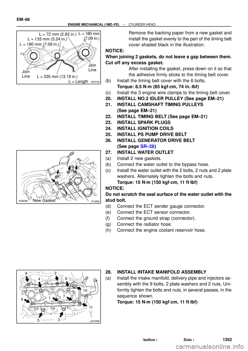
Remove the backing paper from a new gasket and
install the gasket evenly to the part of the timing belt
cover shaded black in the illustration.
NOTICE:
When joining 2 gaskets, do not leave a gap between them.
Cut off any excess gasket.
�After installing the gasket, press down on it so that
the adhesive firmly sticks to the timing belt cover.
(b) Install the timing belt cover with the 6 bolts.
Torque: 8.5 N´m (85 kgf´cm, 74 in.´lbf)
(c) Install the 3 engine wire clamps to the timing belt cover.
20. INSTALL NO.2 IDLER PULLEY (See page EM±21)
21. INSTALL CAMSHAFT TIMING PULLEYS
(See page EM±21)
22. INSTALL TIMING BELT (See page EM±21)
23. INSTALL SPARK PLUGS
24. INSTALL IGNITION COILS
25. INSTALL PS PUMP DRIVE BELT
26. INSTALL GENERATOR DRIVE BELT
(See page SR±28)
27. INSTALL WATER OUTLET
(a) Install 2 new gaskets.
(b) Connect the water outlet to the bypass hose.
(c) Install the water outlet with the 2 bolts, 2 nuts and 2 plate
washers. Alternately tighten the bolts and nuts.
Torque: 15 N´m (150 kgf´cm, 11 ft´lbf)
NOTICE:
Do not scratch the seal surface of the water outlet with the
stud bolt.
(d) Connect the ECT sender gauge connector.
(e) Connect the ECT sensor connector.
(f) Connect the ground strap (connector).
(g) Connect the radiator hose.
(h) Connect the engine coolant reservoir hose.
28. INSTALL INTAKE MANIFOLD ASSEMBLY
(a) Install the intake manifold, delivery pipe and injectors as-
sembly with the 9 bolts, 2 plate washers and 2 nuts. Uni-
formly tighten the bolts and nuts, in several passes, in the
sequence shown.
Torque: 15 N´m (150 kgf´cm, 11 ft´lbf)
Page 3574 of 4770
EM±68
± ENGINE MECHANICAL (1MZ±FE)CYLINDER HEAD
1354 Author�: Date�:
(w) Connect the DLC1 to the bracket on the intake air control
valve.
(x) Connect the accelerator cable.
(y) Connect the A/T throttle cable.
31. INSTALL HIGH±TENSION CORD SET
32. INSTALL V±BANK COVER
33. INSTALL RH ENGINE MOUNTING STAY
(See page EM±76)
34. INSTALL AIR FILTER AND AIR CLEANER CAP
ASSEMBLY
35. INSTALL RH FENDER APRON SEAL
36. INSTALL FRONT EXHAUST PIPE
(See page EM±76)
37. FILL WITH ENGINE COOLANT
38. START ENGINE AND CHECK FOR LEAKS
39. VEHICLE ROAD TEST
Check for abnormal noise, shock, slippage, correct shift points
and smoothly operation.
40. RECHECK ENGINE COOLANT LEVEL
Page 3622 of 4770
BO0L2±01
H01975
Door Lock
Cylinder
Outside Handle Front Door Belt Moulding
Door Glass
Door FrameFront Door Upper Moulding
Outside
Rear View
Mirror
Door Glass
Run
5.5 (55, 49 in.´lbf)
5.5 (55, 49 in.´lbf)
5.0 (50, 43 in.´lbf)�
Door Lock
23 (230, 17)
Window Regulator
8.0 (80, 69 in.´lbf)
Door Hinge
X6
7.5 (75, 66 in.´lbf)
Regulator
Motor
X3
31 (310, 22)
26 (260, 19)
8.0 (80, 71 in.´lbf)
30 (300, 22)
31 (310, 22)
Door
Check
Door Hinge
26 (260, 19)
Speaker
Power Window Switch Rear Lower
FrameFront Lower
FrameFront Window Upper
Garnish
Inside Handle Bezel
3.5 (35, 31 in.´lbf)
Driver's Side:
Regulator
Motor
Ptdt
N´m (kgf´cm, ft´lbf) : Specified torqueInside Handle
Door Trim
� Precoated part Door Lock StrikerService Hole Cover BO±12
± BODYFRONT DOOR
2370 Author�: Date�:
2001 CAMRY (RM819U)
FRONT DOOR
COMPONENTS
Page 3742 of 4770
P12716
SST
SST
P18802
B04136
B04137
P20050Pry LU±10
± LUBRICATION (1MZ±FE)OIL PUMP
1674 Author�: Date�:
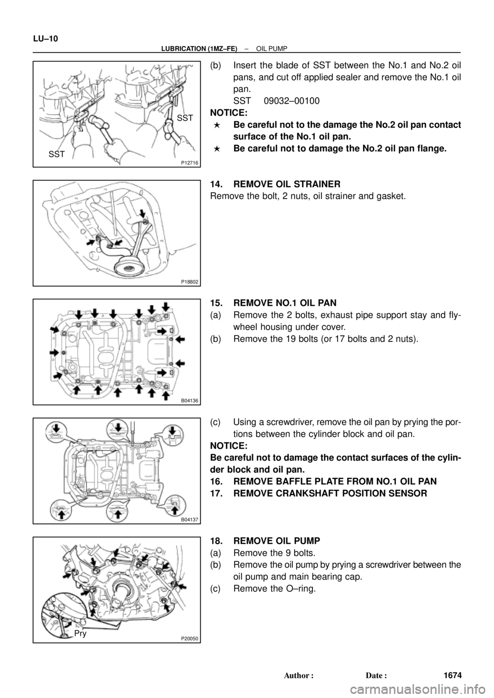
(b) Insert the blade of SST between the No.1 and No.2 oil
pans, and cut off applied sealer and remove the No.1 oil
pan.
SST 09032±00100
NOTICE:
�Be careful not to the damage the No.2 oil pan contact
surface of the No.1 oil pan.
�Be careful not to damage the No.2 oil pan flange.
14. REMOVE OIL STRAINER
Remove the bolt, 2 nuts, oil strainer and gasket.
15. REMOVE NO.1 OIL PAN
(a) Remove the 2 bolts, exhaust pipe support stay and fly-
wheel housing under cover.
(b) Remove the 19 bolts (or 17 bolts and 2 nuts).
(c) Using a screwdriver, remove the oil pan by prying the por-
tions between the cylinder block and oil pan.
NOTICE:
Be careful not to damage the contact surfaces of the cylin-
der block and oil pan.
16. REMOVE BAFFLE PLATE FROM NO.1 OIL PAN
17. REMOVE CRANKSHAFT POSITION SENSOR
18. REMOVE OIL PUMP
(a) Remove the 9 bolts.
(b) Remove the oil pump by prying a screwdriver between the
oil pump and main bearing cap.
(c) Remove the O±ring.
Page 3805 of 4770
MX04Z±01
Q09981
Hood
14 (150, 10)
w/ Cruise Control :
Cruise Control Actuator
12 (120, 9)
Clutch Line Bracket
21 (210, 15)
12 (120, 9)
Clutch Release Cylinder
26 (270, 20)
RH Drive Shaft�
�32 (330, 24)
7.8 (80, 69 in.´lbf)
Flywheel Housing Under CoverRH Fender
Apron SealClutch Accumulator
Vehicle Speed Sensor
Connector
46 (470, 34)
Engine LH Mounting
Insulator with Bracket
Rear RH Suspension Member Brace
37 (380, 27)
Transaxle
64 (650, 47)
36 (370, 27)
10 (100, 7)
Steering Return Pipe
19 (195, 14)
32 (330, 24)
181 (1,850, 134)
Silver Bolt : 44 (450, 33)
Green Bolt : 66 (670, 48)
Suspension Member with
Lower Suspension Arm
Front RH Suspension
Member Brace
181 (1,850, 134)
Control
Cable
Clip13 (130, 9)
Clip
Washer
Starter
21 (210, 15)
39 (400, 29)
Air Cleaner
Case Assembly
with Air Hose
64 (650, 47)Ground Cable
x5Back±Up Light Switch Connector
Engine Wire
20 (200, 14)Hold±Down
Clamp
Battery
LH Drive Shaft
LH Fender Apron Seal RH Exhaust Manifold Stay
64 (650, 47)
181 (1,850, 134)PS Gear Assembly
No.1 Fuel Tube Protector
49 (500, 36)
294 (3,000, 217)
Lock Cap
Rear LH Suspension Member Brace
Stabilizer Bar Link
Hole
Plug
127 (1,300, 94)
39 (400, 29)
80 (820, 59)48 (490, 35)
Silver Bolt : 44 (450, 33)
Green Bolt : 66 (670, 48)
Front LH Suspension
Member Brace RH Fender
Liner
Engine Rear Side
Shutter Plate
56 (570, 41)
�
�
62 (630, 46) �
62 (630, 46) �
Front Exhaust Pipe
No.1 Exhaust Pipe
Support Bracket
33 (330, 24)
Exhaust Pipe Support Stay
33 (330, 24)LH Fender
Liner
66 (670, 48)
Snap Ring
�Snap Ring
�Cotter Pin
�Cotter Pin
�Gasket
�Gasket
�Gasket
Non±reusable part: Specified torque
N´m (kgf´cm, ft´lbf)
�
36 (370, 27)
± MANUAL TRANSAXLE (E153)MANUAL TRANSAXLE UNIT
MX±3
1804 Author�: Date�:
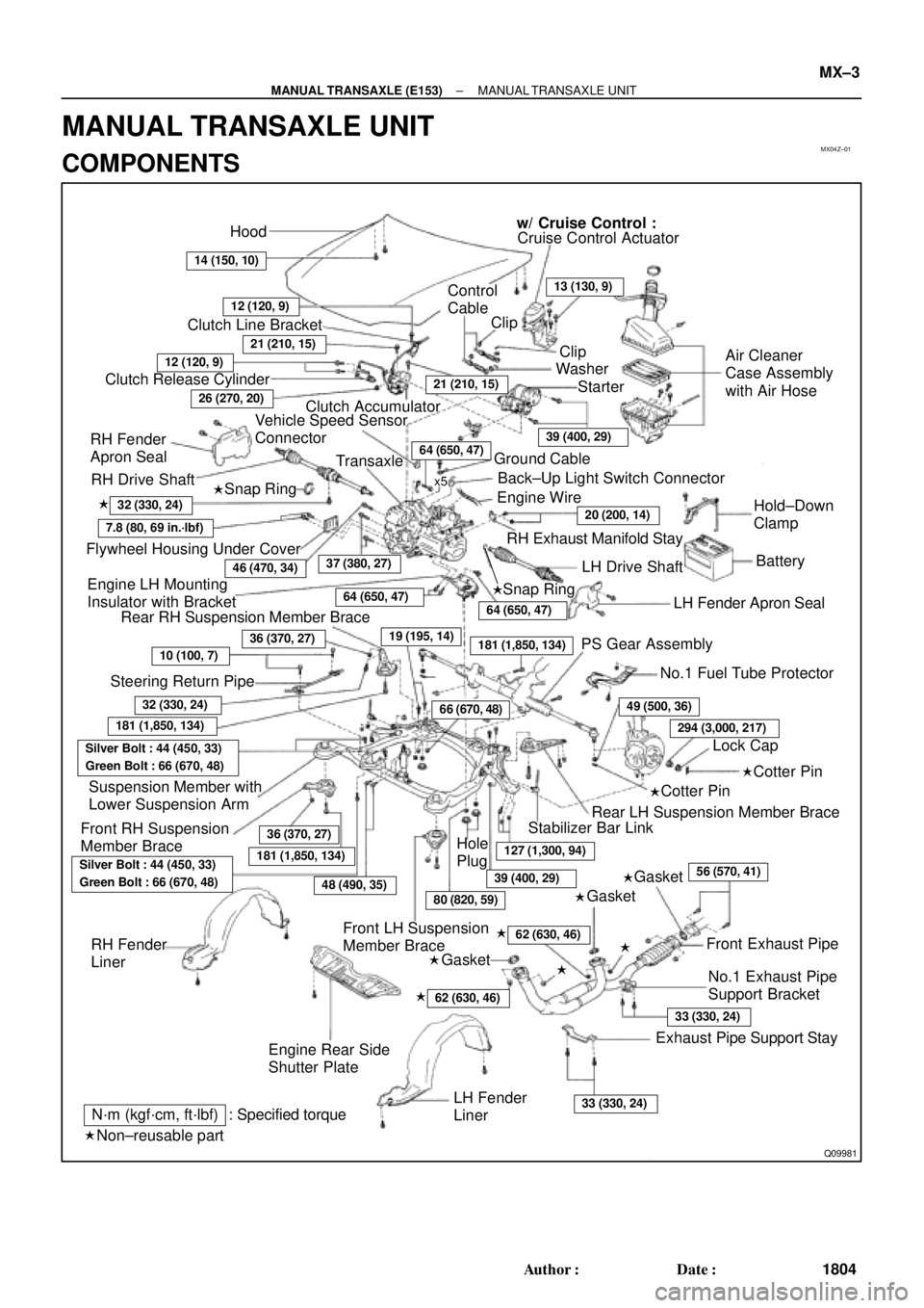
MANUAL TRANSAXLE UNIT
COMPONENTS