Page 3528 of 4770
TIMING BELT
1308 Author�: Date�:
(c) Using SST, install the pulley bolt.
SST 09249±63010, 09960±1")
P20069
Fulcrum
Length
SSTSST RH
P12762
SST LH
P18811
A05063
SST
EM±22
± ENGINE MECHANICAL (1MZ±FE)TIMING BELT
1308 Author�: Date�:
(c) Using SST, install the pulley bolt.
SST 09249±63010, 09960±10010 (09962±01000,
09963±01000)
Torque: 88 N´m (900 kgf´cm, 65 ft´lbf)
HINT:
Use a torque wrench with a fulcrum length of 340 mm (13.39
in.).
5. INSTALL LH CAMSHAFT TIMING PULLEY
(a) Face the flange side of the timing pulley inward.
(b) Align the knock pin on the camshaft with the knock pin
groove of the timing pulley, and slide on the timing pulley.
(c) Using SST, install the pulley bolt.
SST 09960±10010 (09962±01000, 09963±01000)
Torque: 125 N´m (1,300 kgf´cm, 94 ft´lbf)
6. SET NO.1 CYLINDER TO TDC/COMPRESSION
(a) Crankshaft Timing Pulley Position:
Temporarily install the crankshaft pulley bolt to the crank-
shaft.
(b) Crankshaft Timing Pulley Position:
Turn the crankshaft, and align the timing marks of the
crankshaft timing pulley and oil pump body.
(c) Camshaft Timing Pulley Positions:
Using SST, turn the camshaft pulley, align the timing
marks of the timing pulley and No.3 timing belt cover.
SST 09960±10010 (09962±01000, 09963±01000)
Page 3534 of 4770

EGR Gas Temperature
Sensor Connector
Water Bypass Hose
A06657
PS Pressure TubeAir Intake Chamber Stay
V±Bank Cover
VSV Connector
for EGR
Engine Wire�Gasket
No.2 EGR Pipe
Throttle Position
Sensor Connector
Vacuum Hose
EGR Valve Position Brake Booster12 (120,9)
39 (400,29)
�Gasket
Sensor Connector
IAC Valve
ConnectorAccelerator Cable
Throttle Cable
Purge Hose
Air Assist Hose Hose Vacuum
�Gasket
VSV Connector for ACIS
Engine Coolant
Reservoir Hose
43 (440,32)
ECT Sender
Gauge Connector
ECT Sensor
Connector
Grand Strap
Connector
15 (150,11)
Water Outlet
15 (150,11)
Water Bypass
Hose
Upper Radiator
Hose
Fuel Inlet Hose
Injector Connector Intake Manifold Assembly�Retainer
Heater Hose
�Gasket Ignition Coil
Connector
� Non±reusable part: Specified torque
N´m (kgf´cm, ft´lbf)
19.5 (200, 14)
No.1 Engine
Hanger
VSV Connector for
EVAP
Ground Cable
PCV Hose Ground Cable
Air Intake Chamber
Assembly
� Gasket
High±Tension Cord Set
Spark PlugIgnition Coil
Water Bypass Hose
Ground Strap
DLC1
EM±28
± ENGINE MECHANICAL (1MZ±FE)CYLINDER HEAD
1314 Author�: Date�:
Page 3535 of 4770
A05070
Timing Belt
Gasket No.2 Timing Belt Cover
RH Engine Mounting Bracket
Crankshaft
Pulley No.1 Timing Belt Cover
Gasket
Engine Wire
Protector
No.2 Idler Pulley
RH Camshaft Timing Pulley
LH Camshaft
Timing Pulley
Timing Belt TensionerTiming Belt Guide
No.2 Generator
Bracket
Dust Boot
N´m (kgf´cm, ft´lbf) : Specified torque
* For use with SST� Non±reusable part
28 (290, 21)
215 (2,200, 159)
125 (1,300, 94)
*88 (900, 65)
27 (280, 20)
43 (440, 32)
125 (1,300, 94)
± ENGINE MECHANICAL (1MZ±FE)CYLINDER HEAD
EM±29
1315 Author�: Date�:
Page 3536 of 4770
Engine Wire
 ProtectorEngine Wire
Protector
Heated Oxygen Sensor
(Bank 1 Sensor 1)
Connector
RH Exhaust Manifold
(Except")
A06635� Non±reusable part: Specified torque
N´m (kgf´cm, ft´lbf)Engine Wire
Engine Wire ProtectorEngine Wire
Protector
Heated Oxygen Sensor
(Bank 1 Sensor 1)
Connector
RH Exhaust Manifold
(Except M/T and California A/T)
34 (350,25)
x 6
12 (120, 9)
PS Pump Bracket
43 (440, 32)
No.1 EGR Pipe � Gasket
Cylinder Head Rear Plate
Ground Strap
Water Inlet
Pipe � O±Ring
Gasket
20 (200, 14)
CollarBushing No.3 Timing
Belt Cover
x 6
x 6
� O±Ring
49 (500, 36)LH Exhaust
Manifold Stay
(Except M/T and
California A/T ) Oil Dipstick Guide Engine WireRH Exhaust Manifold
RH Exhaust
Manifold Stay
� Gasket
20 (200, 14)
Heated Oxygen Sensor
(Bank 2 Sensor 1)
Connector
34 (350,25)
49 (500, 36)
LH Exhaust
Manifold Stay
LH Exhaust Manifold
California A/T
M/T and California A/T
� Gasket
Camshaft
Position Sensor
ConnectorGasket RH
Exhaust
Manifold
Stay
(Except M/T and Calif. A/T)
Camshaft Position Sensor
LH Exhaust Manifold
(Except California A/T)
49 (500, 36)
x 6 EM±30
± ENGINE MECHANICAL (1MZ±FE)CYLINDER HEAD
1316 Author�: Date�:
Page 3537 of 4770
A02013
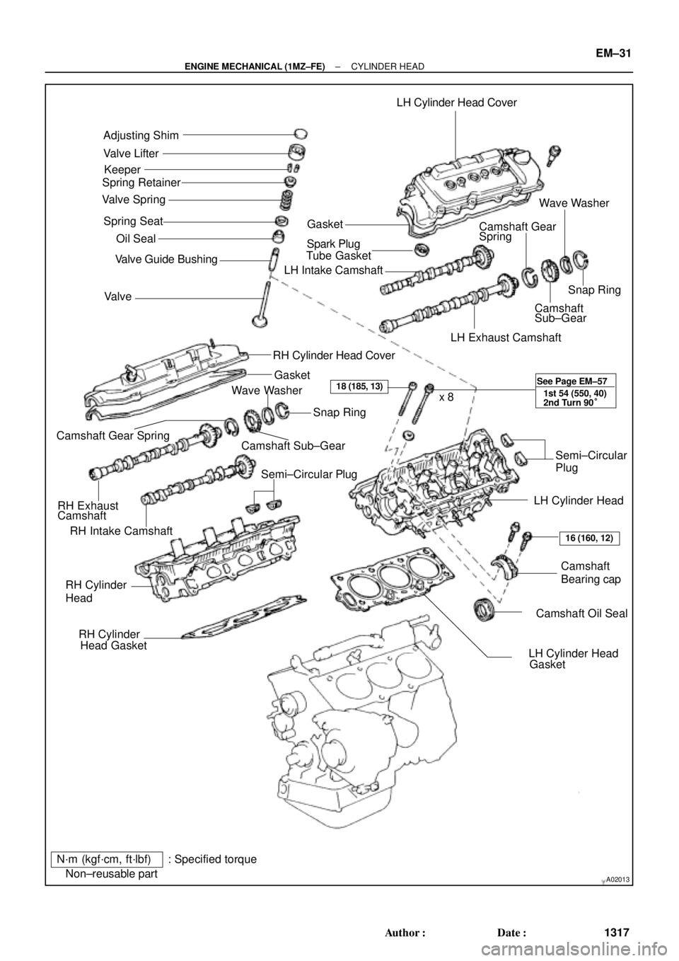
Adjusting Shim
Valve Lifter
Keeper
Spring Retainer
Valve Spring
Spring Seat
� Oil Seal
Valve � Valve Guide BushingLH Cylinder Head Cover
GasketWave Washer
Camshaft Gear
Spring
� Spark Plug
Tube Gasket
LH Intake Camshaft
Snap Ring
Camshaft
Sub±Gear
LH Exhaust Camshaft
RH Cylinder Head Cover
Gasket
RH Intake CamshaftCamshaft Sub±GearSnap Ring
Camshaft Gear Spring
RH Exhaust
CamshaftWave Washer
Semi±Circular PlugSemi±Circular
Plug
LH Cylinder Head
Camshaft
Bearing cap
� Camshaft Oil Seal RH Cylinder
Head
� RH Cylinder
Head Gasket
� LH Cylinder Head
Gasket x 8
N´m (kgf´cm, ft´lbf) : Specified torque
� Non±reusable part
18 (185, 13)
16 (160, 12) See Page EM±57
1st 54 (550, 40)
2nd Turn 90°
± ENGINE MECHANICAL (1MZ±FE)CYLINDER HEAD
EM±31
1317 Author�: Date�:
Page 3538 of 4770

(m) (n)
S05049
(o)
(p)
(q) (s)(r)
(t) EM±32
± ENGINE MECHANICAL (1MZ±FE)CYLINDER HEAD
1318 Author�: Date�:
REMOVAL
1. DRAIN ENGINE COOLANT
2. REMOVE AIR CLE")
EM04S±05
S04528
Hexagon
Clip
A06658
(l)
(m) (n)
S05049
(o)
(p)
(q) (s)(r)
(t) EM±32
± ENGINE MECHANICAL (1MZ±FE)CYLINDER HEAD
1318 Author�: Date�:
REMOVAL
1. DRAIN ENGINE COOLANT
2. REMOVE AIR CLEANER CAP ASSEMBLY AND AIR
FILTER
3. REMOVE ENGINE RH FENDER APRON SEAL
4. REMOVE FRONT EXHAUST PIPE (See page EM±71)
5. REMOVE RH ENGINE MOUNTING STAY
6. REMOVE V±BANK COVER
(a) Using a 5 mm hexagon wrench, remove the 2 nuts.
(b) Disconnect the 2 clips, and remove the cover.
7. REMOVE HIGH±TENSION CORD SET
(See page IG±7)
8. REMOVE AIR INTAKE CHAMBER ASSEMBLY
(a) Disconnect the accelerator cable.
(b) Disconnect the A/T throttle cable.
(c) Disconnect the throttle position sensor connector.
(d) Disconnect the IAC valve connector.
(e) Disconnect the EGR gas temperature sensor connector.
(f) Disconnect the EGR valve position sensor connector.
(g) Disconnect the VSV connector for the ACIS.
(h) Disconnect the VSV connector for the EVAP.
(i) Disconnect the VSV connector for the EGR.
(j) Disconnect the DLC1 from the bracket on the intake air
control valve.
(k) Remove the 2 nuts, and disconnect the PS pressure tube
from the No.1 engine hanger.
(l) Disconnect the PCV hose from the PCV valve on the RH
cylinder head.
(m) Disconnect the ground strap and cable from the intake air
control valve for the ACIS.
(n) Disconnect the ground cable from the air intake chamber.
(o) Disconnect the brake booster vacuum hose from the air
intake chamber.
(p) Disconnect the 2 water bypass hoses from the throttle
body.
(q) Disconnect the air assist hose from the throttle body.
(r) Disconnect the purge hose from the pipe on emission
control valve set.
(s) Disconnect the 2 vacuum hoses from the vacuum tank for
the ACIS.
Page 3540 of 4770
CYLINDER HEAD
1320 Author�: Date�:
10. REMOVE WATER OUTLET
(a) Disconnect the ECT sender gauge connector.
(b) Disconne")
P20049Gasket
A05077
Clamp
Clamp
Clamp
S04786
EM±34
± ENGINE MECHANICAL (1MZ±FE)CYLINDER HEAD
1320 Author�: Date�:
10. REMOVE WATER OUTLET
(a) Disconnect the ECT sender gauge connector.
(b) Disconnect the ECT sensor connector.
(c) Disconnect the ground strap (connector).
(d) Disconnect the radiator hose.
(e) Disconnect the engine coolant reservoir hose.
(f) Remove the 2 bolts, 2 nuts and 2 plate washers.
(g) Disconnect the water bypass hose, and remove the water
outlet.
(h) Remove the 2 gaskets.
11. REMOVE GENERATOR DRIVE BELT
(See page CH±6)
12. REMOVE PS PUMP (See page SR±21)
13. REMOVE IGNITION COILS
14. REMOVE SPARK PLUGS
15. REMOVE TIMING BELT (See page EM±15)
16. REMOVE CAMSHAFT TIMING PULLEYS
(See page EM±15)
17. REMOVE NO.2 IDLER PULLEY (See page EM±15)
18. REMOVE NO.3 TIMING BELT COVER
(a) Disconnect the 3 engine wire clamps from the timing belt
cover.
(b) Remove the 6 bolts and timing belt cover.
19. DISCONNECT ENGINE WIRE PROTECTOR FROM
REAR SIDE
Remove the 2 nuts, and disconnect the engine wire protector
from the RH cylinder head and water inlet.
Page 3541 of 4770
S04787
A01812
S04789
Rear
Plate
Ground
Strap
Inlet Pipe
P18773
± ENGINE MECHANICAL (1MZ±FE)CYLINDER HEAD
EM±35
1321 Author�: Date�:
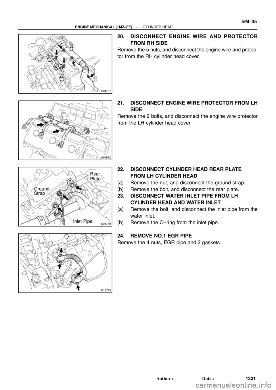
20. DISCONNECT ENGINE WIRE AND PROTECTOR
FROM RH SIDE
Remove the 5 nuts, and disconnect the engine wire and protec-
tor from the RH cylinder head cover.
21. DISCONNECT ENGINE WIRE PROTECTOR FROM LH
SIDE
Remove the 2 bolts, and disconnect the engine wire protector
from the LH cylinder head cover.
22. DISCONNECT CYLINDER HEAD REAR PLATE
FROM LH CYLINDER HEAD
(a) Remove the nut, and disconnect the ground strap.
(b) Remove the bolt, and disconnect the rear plate.
23. DISCONNECT WATER INLET PIPE FROM LH
CYLINDER HEAD AND WATER INLET
(a) Remove the bolt, and disconnect the inlet pipe from the
water inlet.
(b) Remove the O±ring from the inlet pipe.
24. REMOVE NO.1 EGR PIPE
Remove the 4 nuts, EGR pipe and 2 gaskets.