Page 4010 of 4770

211 Author�: Date�:
TORQUE SPECIFICATION
Part tightenedN´mkgf´cmft´lbf
Transaxle x Engine 17 mm head
14 mm head A
(See page MX±4)")
SS09P±01
SS±48
± SERVICE SPECIFICATIONSMANUAL TRANSAXLE (E153)
211 Author�: Date�:
TORQUE SPECIFICATION
Part tightenedN´mkgf´cmft´lbf
Transaxle x Engine 17 mm head
14 mm head A
(See page MX±4) 14 mm head B64
46
37650
470
38047
34
27
Cruise control actuator x Body (w/ Cruise control)131309
Starter x Transaxle3940029
Clutch release cylinder x Transaxle121209
Clutch acummulator x Transaxle Bolt
Nut21
26210
27015
20
Clutch line bracket x Transaxle121209
Front wheel1031,05076
Exhaust pipe support stay3333024
Front exhaust pipe x Exhaust manifold6263046
Front exhaust pipe x Center exhaust pipe5657041
No.1 exhaust pipe support bracket x Front suspension member3333024
Stabilizer bar link x Stabilizer bar3940029
Stabilizer bar bracket x Front suspension member1919514
PS gear assembly x Front suspension member1811,850134
Front engine absorber x Transaxle4849035
RH exhaust manifold stay2020014
Front engine mounting insulator x Front suspension member Silver bolt
Green bolt44
66450
67033
48
LH engine mounting insulator x Front suspension member8082059
LH engine mounting bracket x Transaxle6465047
Rear engine mounting insulator x Front suspension member6667048
Steering return pipe x Front suspension member101007
Front suspension member with lower suspension arm Bolt A
Bolt B
(See page MX±4) Nut C181
32
361,850
330
370134
24
27
Flywheel housing under cover x Transaxle7.88069 in.´lbf
Shift cable grommet retainer x Body4.95043 in.´lbf
Shift lever assembly x Body121209
No.2 selecting bellcrank with selecting bellcrank support2020014
Shift and select lever shaft lock bolt4950036
Shift and select lever shaft assembly x Transmission case2020014
Transmission case cover x Transmission case2930022
Breather plug4950036
Output shaft lock nut1231,25090
Shift fork and shift head set bolt2424017
Rear bearing retainer x Transmission case4243031
Straight screw plug2525018
Straight screw plug (Reverse restrict pin)131309
Reverse idler gear shaft lock bolt2930022
Transmission case x Transaxle case2930022
Transmission oil pipe x Transaxle case1717513
Reverse shift arm bracket assembly x Transaxle case1717513
Page 4014 of 4770

215 Author�: Date�:
TORQUE SPECIFICATION
Part tightenedN´mkgf´cmft´lbf
Transaxle x Engine 17 mm head6465047Transaxle x Engine 17 mm")
SS09N±01
SS±52
± SERVICE SPECIFICATIONSMANUAL TRANSAXLE (S51)
215 Author�: Date�:
TORQUE SPECIFICATION
Part tightenedN´mkgf´cmft´lbf
Transaxle x Engine 17 mm head6465047Transaxle x Engine 17 mm head
14 mm head
64
46
650
470
47
34
Cruise control actuator x Body (w/ Cruise control)131309
Starter x Transaxle3737828
Clutch release cylinder x Transaxle121209
Clutch line bracket x Transaxle Bolt A121209Clutch line bracket x Transaxle Bolt A
(See page MX±4) Bolt B
12
6.9
120
70
9
61 in.´lbf
Manifold stay Front side4242531
Manifold stay Rear side3940029
Front wheel1031,05076
Exhaust pipe bracket Bolt1919514Exhaust ie bracket Bolt
Nut
19
33
195
330
14
24
Front exhaust pipe x Exhaust manifold6263046
Front exhaust pipe x Center exhaust pipe5657041
No.1 exhaust pipe support bracket x Front suspension member3333024
Stabilizer bar link x Stabilizer bar3940029
Stabilizer bar bracket x Front suspension member1919514
PS gear assembly x Front suspension member1811,850134
Front engine mounting insulator x Front suspension member Silver bolt4445033Front engine mounting insulator x Front sus ension member Silver bolt
Green bolt
44
66
450
670
33
48
LH engine mounting insulator x Front suspension member8082059
LH engine mounting bracket x Transaxle6465047
Rear engine mounting insulator x Front suspension member6667048
Steering return pipe x Front suspension member101007
Front suspension member with lower suspension arm Bolt A1811,850134Front sus ension member with lower sus ension arm Bolt A
Bolt B
181
32
1,850
330
134
24Bolt B
(See page MX±4) Nut C
32
36
330
370
24
27
LH stiffener plate3738027
RH stiffener plate3940029
Rear end plate9.39582 in.´lbf
Shift cable grommet retainer x Body4.95043 in.´lbf
Shift lever assembly x Body121209
Transmission case x Transaxle case2930022
Transmission case x Case cover2930022
Transmission case protector1818513
Rear bearing retainer4243031
Output shaft front bearing lock plate1818513
Transaxle case receiver set bolt7.47565 in.´lbf
5th driven gear lock nut1231,25090
Reverse idler shaft lock bolt2930022
Control shaft cover3737527
Control shift lever x Lever shaft6.46556 in.´lbf
Ring gear x Differential case8385061
Selecting bellcrank x Transmission case3738027
Page 4038 of 4770
SFI SYSTEM
1437 Author�:")
Z11336
California
Except CaliforniaGrommetInsulator O±Ring
InjectorO±Ring
O±Ring
Grommet
InjectorInsulator
S04583
Pull
S05040
Vinyl Bag
S05382
Retainer
SF±4
± SFI (5S±FE)SFI SYSTEM
1437 Author�: Date�:
(e) Install the injector to the delivery pipe and cylinder head,
as shown in the illustration.
Before installing the injector, must apply spindle oil or gas-
oline on the place where a delivery pipe or an intake man-
ifold touches an O±ring of the injector.
(f) Observe these precautions when disconnecting the fuel
tube connector (quick type):
(1) Check if there is any dirt like mud on the pipe and
around the connector before disconnecting them
and clean the dirt away.
(2) Be sure to disconnect with hands.
(3) When the connector and the pipe are stuck, pinch
the retainer between the hands, push and pull the
connector to free to disconnect and pull it out. Do
not use any tool at this time.
(4) Inspect if there is any dirt or the likes on the seal sur-
face of the disconnected pipe and clean it away.
(5) Prevent the disconnected pipe and connector from
damaging and mixing foreign objects by covering
them with a vinyl bag.
(g) Observe these precautions when connecting the fuel
tube connector (quick type):
(1) Do not reuse the retainer removed from the pipe.
(2) Must use hands without using tools when to remove
the retainer from the pipe.
(3) Check if there is any damage or foreign objects on
the connected part of the pipe.
Page 4055 of 4770
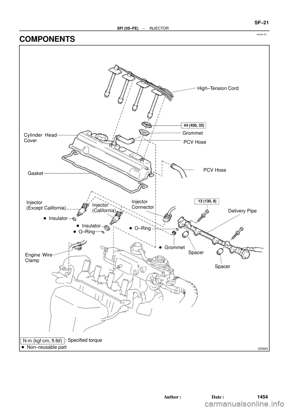
SF0DH±03
N´m (kgf´cm, ft´lbf)
S05925
Cylinder Head
Cover
Gasket
Injector
(Except California)
� Insulator
Engine Wire
ClampHigh±Tension Cord
Grommet
PCV Hose
Delivery Pipe Injector
Connector Injector
(California)
Spacer
Spacer � Insulator
� O±Ring� O±Ring
� Grommet
� Non±reusable part
44 (450, 33)
13 (130, 9)
PCV Hose
: Specified torque
± SFI (5S±FE)INJECTOR
SF±21
1454 Author�: Date�:
COMPONENTS
Page 4056 of 4770

(e)
(d)
B06353
B06354
SF±22
± SFI (5S±FE)INJECTOR
1455 Author�: Date�:
REMOVAL
1. REMOVE CYLINDER HEAD COVER
(a) Disconnect the 4 high±tension cords from the clamps on
the cy")
SF0DI±03
S05289
(c)
(e)
(d)
B06353
B06354
SF±22
± SFI (5S±FE)INJECTOR
1455 Author�: Date�:
REMOVAL
1. REMOVE CYLINDER HEAD COVER
(a) Disconnect the 4 high±tension cords from the clamps on
the cylinder head cover.
(b) Disconnect the 4 high±tension cords from the spark
plugs.
(c) Disconnect the PCV hose from the intake manifold.
(d) Disconnect the PCV hose from the cylinder head cover.
(e) Disconnect the engine wire clamp from the mounting bolt
of the No.2 timing belt cover.
(f) Remove the cylinder head cover. (See page EM±33)
NOTICE:
Cover the cylinder head with a clean cloth to prevent dirt,
etc. getting into the cylinder head.
2. REMOVE DELIVERY PIPE AND INJECTORS
(a) Disconnect the 4 injector connectors.
(b) Remove the 2 bolts holding the delivery pipe to the cylin-
der head.
(c) Disconnect the delivery pipe from the 4 injectors.
(d) Pull out the 4 injectors.
NOTICE:
Be careful not to drop the injectors.
(e) Remove the 4 insulators (Except California) and 2
spacers from the cylinder head.
(f) California:
Remove the 2 O±rings, insulator and grommet from each
injector.
(g) Except California:
Remove the O±ring and grommet from each injector.
Page 4060 of 4770

(c) (d) SF±26
± SFI (5S±FE)INJECTOR
1459 Author�: Date�:
(h) Attach the 4 injectors and delivery pipe assembly t")
B06352
S05976
Upward
Turn
Connector
B06351
Gray
Brown No.1
No.2
No.3
No.4
S05289
(b)
(c) (d) SF±26
± SFI (5S±FE)INJECTOR
1459 Author�: Date�:
(h) Attach the 4 injectors and delivery pipe assembly to the
cylinder head.
(i) Temporarily install the 2 bolts holding the delivery pipe to
the cylinder head.
(j) Check that the injectors rotate smoothly.
HINT:
If injectors do not rotate smoothly, the probable cause is incor-
rect installation of O±rings. Replace the O±rings.
(k) Position the injector connector upward.
(l) Tighten the 2 bolts holding the delivery pipe to the cylinder
head.
Torque: 13 N´m (130 kgf´cm, 9 ft´lbf)
(m) Connect the 4 injector connectors.
HINT:
The No.1 and No.3 injector connectors are brown, and the No.2
and No.4 injector connectors are gray.
2. INSTALL CYLINDER HEAD COVER
(a) Install the cylinder head cover. (See page EM±53)
(b) Connect the PCV hose to the intake manifold.
(c) Connect the PCV hose to the cylinder head cover.
(d) Install the engine wire clamp to the mounting bolt of the
No.2 timing belt cover.
(e) Connect the 4 high±tension cords to the spark plugs.
(f) Install the 4 high±tension cords to the clamps on the cylin-
der head cover.
3. CHECK FOR FUEL LEAKS (See page SF±1)
Page 4511 of 4770
, 98 - 01 Sienna,
99 - 01 Solara & 01 Avalon
Technical Service
BULLETIN
November 3, 2000")
Toyota Supports ASE CertificationPage 1 of 1
BO028-00Title:
LEAKS INTO TRUNK
Models:
'97 - '01 Camry (U.S.), '98 - '01 Sienna,
'99 - '01 Solara & '01 Avalon
Technical Service
BULLETIN
November 3, 2000
A field fix is available for incidents of moisture and odors permeating into the vehicle.
The Quarter Panel Air Duct flaps may have become loose or missing. Replacing the
Quarter Panel Air Duct will remedy the condition.
�1997 ± 2001 model year Camry (U.S. produced)
�1998 ± 2001 model year Sienna
�1999 ± 2001 model year Solara
�2001 model year Avalon
MODELSTARTING VIN
2001 MY Camry, 4 cylinder4T1BG22K81U019710
4T1BG22KB1U768622
2001 MY Camry, 6 cylinder4T1BF28K11U116208
4T1BF22K51U958204
2001 MY Sienna4T3ZF13C#1U335575
2001 MY Solara2T1CF22P#1C435983
2001 MY Solara Convertible2T1FF28P#1C435448
2001 MY Avalon4T1BF28B11U123532
PREVIOUS PART NUMBERCURRENT PART NUMBERPART NAME
62940-AA01062940-AA011Quarter Panel Air Duct
Replace the Quarter Panel Air Duct.
OP CODEDESCRIPTIONTIMEOPNT1T2
BD0036R & R Quarter Panel Air Duct1.062940-AA0106257
Applicable Warranty*:
This repair is covered under the Toyota Basic Warranty. This warranty is in effect for
36 months or 36,000 miles, whichever occurs first, from the vehicle's in-service date.
* Warranty application is limited to correction of a problem based upon a customer's specific complaint.
BODY
Introduction
Applicable
Vehicles
Production
Change
Information
Parts
Information
Repair
Procedure
Warranty
Information
Page 4523 of 4770

Toyota Supports ASE CertificationPage 1 of 1
BR004±99
Title:
REAR BRAKE DRUM NOISE
Models:
'99 Camry ± NAP
Technical Service
BULLETIN
July 16, 1999
Rear Brake Drums are available to reduce rear brake drum howling/groaning noise on
NAP built Camrys.
�1999 4 cylinder NAP built Camrys built before:
4T1BG2 * K * XU568428 (NAP ± Plant 1)
4T1BG2 * K * XU900266 (NAP ± Plant 2)
PART NUMBERPART NAME
42431±33020Rear Brake Drum
If the customer encounters a brake groan or howling noise, replace the rear brake drums.
OP CODECOMBODESCRIPTIONTIMEOPNT1T2
472151AR & R Rear Brake Drum (Both Sides)1.142431±330209199
Applicable Warranty*:
This repair is covered under the Toyota Basic Warranty. This warranty is in effect for
36 months or 36,000 miles, whichever occurs first, from the vehicle's in±service date.
* Warranty application is limited to correction of a problem based upon a customer's specific complaint.
BRAKES
Introduction
Applicable
Vehicles
Parts
Information
Repair
Procedure
Warranty
Information